Usually the first step toward learning development on a micro-controller is simply blinking a LED, as an analog to “Hello, world!” example used on PC programming languages. This time we will have a look into how to start programming and development on STMicroelectronics STM8 series of micro-controllers.
What you need?
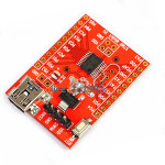
In order to start, obviously you need a development board of some sort (ST’s STM8 Discovery evaluation board is a good pick, or you can get away with el-cheapo chinese boards which are going for around 2$ including shipping!) and obviously a programmer to write your compiled code into the micro-controller.
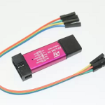
For the programmer, you need one that support SWIM (Single Wire Interface Module) mode. You can (recommended) go with the original debugger of STMicroelectronics which is ST-Link V2 (you can get this one second hand as low as 20$) or if you are really want to go economical, you can get away with the fake ones wich cost you under 10$ (please note that these cheap debuggers only support software mode, which works fine, and do not give you full functionality and speed of the genuine debuggers of ST itself).
One more thing that you need, is the development environment and compiler. If you are on Windows, I recommend to get the code-size limited version of IAR Embedded Workbench. If you are on linux, things are a bit more complex (I will do a separate tutorial for linux as soon as possible).
Start the job!
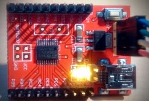
For this tutorial, I am using an evaluation board which is based on STM8S003F3 micro-controller. This should not make any difference for all other chips in STM8 series, as long as you know which PIN is your LED or LEDS are connected to. In this case, the LED on my board is connected to PortD, Bit 3 which reads PD3 on the PCB.
The first step is to configure the PD3 pin (or whichever pin your LED is connected to).
|
1 2 3 4 5 6 |
PD_ODR = 0; //Turn off all pins PD_DDR_DDR3 = 1; //PortD, Bit 3 is output (PD3 - Data Direction Register) PD_CR1_C13 = 1; //PortD, Control Register 1, Bit 3 (PD3) set to Push-Pull PD_CR2_C23 = 1; //PortD, Control Register 2, Bit 3 (PD3) set to Push-Pull |
The code above configure the PD3 pin (Port D, Pin or Bit 3). If your LED is connected to something else, e.g. PC1, then your code should look like this:
|
1 2 3 4 5 6 |
PC_ODR = 0; //Turn off all pins of Port C PC_DDR_DDR1 = 1; //PortC, Bit 1 is output (PC1 - Data Direction Register) PC_CR1_C11 = 1; //PortC, Control Register 1, Bit 3 (PC1) set to Push-Pull PC_CR2_C21 = 1; //PortC, Control Register 2, Bit 3 (PC1) set to Push-Pull |
Just compare the two code snippets above, I am sure you will figure out how to change it to work on any port and bit that you like!
Next, we need a very simple delay function, two insert a pause between ON and OFF state of our LED!
|
1 2 3 4 5 6 |
void delay(unsigned int n) { while (n-- > 0); } |
The above delay, is just a counter which decrements the value you gave to it until it reaches 0. This is a naive delay, and actual time would be based on clock configuration, and how much time the instruction for decrementing the given value and comparing it to 0 would take. But it will suffice for our work today!
Putting everything together, your main.c should look like this.
|
1 2 3 4 5 6 7 8 9 10 11 12 13 14 15 16 17 18 19 20 21 22 23 24 25 |
#include <iostm8s003f3.h> void delay(unsigned int n) { while (n-- > 0); } //main entry point int main( void ) { PD_ODR = 0; //Turn off all pins PD_DDR_DDR3 = 1; //PortD, Bit 3 is output (PD3 - Data Direction Register) PD_CR1_C13 = 1; //PortD, Control Register 1, Bit 3 (PD3) set to Push-Pull PD_CR2_C23 = 1; //PortD, Control Register 2, Bit 3 (PD3) set to Push-Pull while (1) { //Turn on and off the output and then delay PD_ODR_bit.ODR3 = !PD_ODR_bit.ODR3; delay(30000); } } |
You notice the include directive on the first line of the code, in this case, it is provided by IAR STM8. Alternatively you can download the full standard library for STM8 from ST website.
At the end, you should have a blinking led on your board. If you faced any problem, just let me know in the comments and I will try to help you out.
For more in-depth explanation, jump to Part 2 to learn how to setup a pin as input, to be able to detect button press.



I get unable to connect to target! 🙁
I have the same board and a cheap ST-Link2 clone. I got the same message with IAR and ST Visual Develop.
I have also another board, smaller and blue, same message. It says that the chip not answer.
ST-Link2 clone works with STM32 boards but I wasn’t able to made it works with STM8.
Are you sure that you are using IAR for STM8? IAR has different versions for STM8 and STM32.
Alternatively you may try it on linux using stm8flash program. I got the guide here: http://embedonix.com/articles/linux/setting-up-development-and-programming-for-stm8-on-linux/
I did this tutorial successfully and I really enjoyed it–THANK YOU–; the only disturbing thing which is not stated here was to disable the optimizer of the IAR to implement required delays. Because IAR is set to the highest possible optimization grade by default and omits the delay(not useful!) part! To make this not happen, you can do as the following:
1-Go to : Project > Options > C/C++ Compiler > Optimizations
2- Set the level to “None” and then press OK.
3- Rebuild the project
4- It’s done!
Good Luck.
Or declare the counter as volatile so that the compiler would not optimize it out.
Pingback: راه اندازیی برد Stm8s با اردینو
Hi, Yours is the first tutorial I am reading for STM8 programming. Thanks.
I have a question though. You use IAR (someone mentioned also ST visual develop)
For other reasons,(I am also working with STM32 nucleos and stuff) I am thinking of installing Eclipse and GCC ARM. So that will take space of my hard disk.
Do you think that I can program STM8 with eclipse too? (with the appropriate -if they exist- plug ins I suppose)
Thanks
Yes, you can program/debug STM8 using eclipse too. But if there is no ready plugin for eclipse, it is gonna be up to you to configure your project, set the path to headers and include files, tell eclipse which compiler to use and so on. Eclipse is just an (highly customizable) IDE which you can pretty much write any code and compile it, granted you have set the right settings!
Thank you for your reply.
I installed ST Visual develop instead with Cosmic Compiler.
Is the code you posted here exclusive for IAR?
Yes, the code here is for IAR compiler. But the idea is the same, just include the appropriate header files for your chip from cosmic libraries and follow the same principles!
Hello,
Can you elaborate on the differences between the original ST Link v2 and the clone version, particularly that the clone version only supports software mode… of what etc?
Thanks, Ian
The clone just works…it is however is not reliable for debugging…sometimes it halts the core or misses debug points. If you want 100% reliability you should go for original of course
Link library for STM8S003F3 here https://youtu.be/SJYy8WWx9gE
Why dose initial other register CR1&CR2?
{
PD_ODR=0x08;
while
{
PD_ODR&=0x08;
}
}
I did not understand what you mean!
is it possible to compile stm8s003f3 on linux?
Yes, you can check HERE
is there is a complete tutorial explain ADC,PWM,INTERUPT,
There are some tutorials on youtube from another guy. If you want to get going faster, you need to get involved with the datasheet, reference manual and programming manual.
why you set control register 1 and 2 to be 1(push and pull) what will happen if you do not set these register.
for lighting the led the pin need to be push-pull to allow current flowing out of the pin.
If you do not set the register bits, they will have their reset value specified on datasheet.
Hello
I know this must be a really stupid question but how do you download your program to the board in IAR EWARM? So far I see a green triangle but this is for debug. I don’t want it to debug, just run for ever
Thanks
It is not a stupid question at all! First, you need to follow the guidelines on this page provided by IAR:
https://www.iar.com/support/tech-notes/debugger/application-does-not-run-stand-alone/
Then, you probably need to write the resulted binary file using ST LINK software directly on the chip on flash area.
Thanks for kindly answering my question
I have another one, don’t expect a solution but rather ideas from your own experience.
I am debugging some code I did not write for STM8 in IAR. When I run it, I get the disassembly window with a green line there (as expected). It is supposed I should also get something similar in the code window in order to debug line by line. but I don’t. I can not set breakpoints either. Has this ever happened to you?
Any idea why this could be happening?
Thanks!
I tried to change delay and there is some tricky thing.
When delay=10000 led blinks fast.
When delay=50000 led blinks slow.
When delay=90000 led blinks fast again.
Why is it so?
Hmmm it’s look like an overflow issue
hey ,i run the code & face this error:
“Failed to set ROP flag ”
what should i do?
Hello sir, can you explain how is the wiring between stm8s and the st link ?