

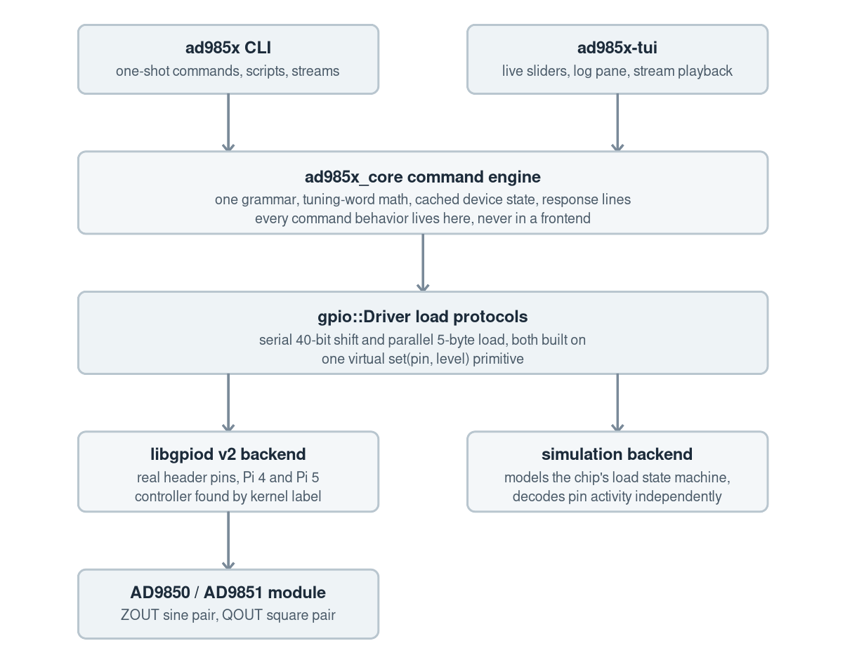
Part 3 of 4. Page 2 covered the CLI, TUI, response lines, and the failure modes that shaped the workflow. This page covers the C++ structure behind it: one static core library, two frontends, libgpiod v2 for real pins, and a simulation backend for CI and development.
One command engine behind both frontends
The project has two frontends because they solve different bench problems. The CLI belongs in scripts, sweep files, and SSH sessions. The TUI belongs at the scope, where changing frequency, toggling power, or sending a raw word should not require rewriting a shell command every few seconds.
The important design choice is that neither frontend owns DDS behavior. Both feed commands into one engine library. That engine parses the command, updates or loads the cached state, validates the resulting word, and calls the GPIO driver. The CLI prints response lines. The TUI renders controls and a response log. Neither frontend gets its own idea of what reset, power-down, raw input, or phase change means.
The chip-specific facts sit in a small profile. That keeps the tuning-word math and W0 policy centralized instead of scattered through option parsing, raw-byte handling, and UI code.
Why the core is a static C++ library
The repository builds a real core library, not a pile of files copied into two executables. In CMake it is an ad985x_core static library, and both frontends link against it:
|
1 2 3 4 5 6 7 8 9 10 11 12 13 14 15 16 |
add_library(ad985x_core STATIC dds.cpp engine.cpp gpio.cpp options.cpp state.cpp ) add_executable(ad985x src/cli/main.cpp) target_link_libraries(ad985x PRIVATE ad985x_core) add_executable(ad985x-tui src/tui/app.cpp src/tui/main.cpp) target_link_libraries(ad985x-tui PRIVATE ad985x_core ftxui::component) |
A shared library would also work, but it would not buy much for this project. The Pi-side tool is small, the public ABI is not meant to be consumed by unrelated programs, and a static core avoids runtime library path problems when the binaries are copied onto a bench machine. The important point is the library boundary, not whether the final link step is static or dynamic: chip math, state caching, command parsing, GPIO protocol, and simulation live in one reusable unit.
That boundary also makes the code easier to test. The pure DDS math in dds.cpp has no GPIO dependency. The engine can be exercised through text commands. The GPIO driver can be swapped between libgpiod and simulation behind the same pin-level interface. The CLI and TUI then become users of the library instead of owners of the behavior.
|
1 2 3 4 5 6 7 8 9 10 11 12 13 14 15 16 17 18 19 20 21 22 |
// Chip selection plus clocking. This decides SYSCLK and FTW conversion. struct Profile { Chip chip = Chip::AD9850; bool pll6 = false; double refclk_hz = 125000000.0; // Note: AD9851 can multiply REFCLK by 6. AD9850 cannot. double sysclk_hz() const { return refclk_hz * ((chip == Chip::AD9851 && pll6) ? 6.0 : 1.0); } }; // One complete loadable DDS state. struct DeviceState { uint32_t ftw = 0; uint8_t phase_word = 0; bool power_down = false; bool pll6 = false; }; |
The AD9851 PLL bit is only allowed when the selected profile says the chip is an AD9851. On an AD9850, the same bit must stay clear. That rule belongs near the profile and validation code, not in the UI.
The CLI is a protocol adapter
The command-line executable mostly maps shell arguments into the engine’s line-oriented command grammar. That grammar is intentionally boring: FREQ, PHASE, PWR, RESET, RAW, DRYRUN, STATUS, and CAPS. The same text lines are used by stream files, by the CLI, and internally by the TUI.
That means the CLI has a clear job: parse process arguments, open one engine session, execute one command or stream, print OK lines to stdout, print WARN and ERR lines to stderr, and return a useful exit code. It does not know how to compute a tuning word. It does not know how serial mode is entered. It does not know how to repair state after reset. Those rules live in the core because scripts and the TUI need the same behavior.
The TUI is another client of the same engine
The TUI is built with FTXUI, but it is not a separate DDS controller. It keeps one engine session open while the screen is active, sends the same command strings that the CLI would send, and parses the same response lines back into sliders, raw-byte fields, status labels, and the response log.
That matters at the bench. If dragging a TUI slider used a private code path while a shell command used another, the first real bug would be deciding which interface was telling the truth. Here the TUI is a richer control surface over the same library. It adds interaction, throttling for live slider updates, keyboard handling, and log presentation, but the DDS behavior is still owned by the core.
The state cache is there because the chip has none
Every load writes the whole 40-bit word. A power-only command still needs the last frequency tuning word. A phase-only command does too. Because the AD9850 has no readback, the software stores the last programmed state in a small cache file shared by the CLI and TUI.
That cache is not treated as truth from the silicon. It is the software’s best record of what it last attempted to program. To avoid silent reinterpretation, the cache records the chip profile that wrote it. If a later run uses a different chip or reference clock, the tool warns instead of pretending the old tuning word has the same meaning.
The cache behavior matches the device behavior where it matters. Power-down keeps the tuning word. Reset clears the load state. An explicit reload sends the word again even when it matches the cache.
GPIO line handling on modern Raspberry Pi OS
The GPIO backend uses libgpiod v2 and the kernel character device interface. It does not use the removed sysfs GPIO API, and it does not depend on older Pi GPIO wrappers. That choice keeps the tool aligned with current Raspberry Pi OS releases.
One practical detail matters for Pi compatibility: the code finds the header GPIO controller by kernel label rather than hardcoded gpiochip number, because the Raspberry Pi 5 RP1 controller has moved between chip numbers across kernel versions. A tool that assumes /dev/gpiochip0 or /dev/gpiochip4 will work on one image and fail on another. Looking for labels such as pinctrl-rp1 and pinctrl-bcm2711 is a small Linux detail that prevents a very irritating field failure.
Serial mode also uses libgpiod bias settings for the strap lines by default. During the mode-entry pulse, D0 and D1 need to read high and D2 needs to read low. For the bench prototype I used Raspberry Pi GPIOs with internal pulls: D0 and D1 as input pull-up, and D2 as input pull-down. That is convenient for jumper-wire testing and allows the same header to later support parallel mode.
For a PCB or unattended instrument, do not rely on Raspberry Pi internal pulls for mode selection. Those pulls are configured only after Linux boots and the program requests the GPIO lines. Hard-strap the mode pins instead: D0 and D1 to 3.3 V through 10 kΩ, and D2 to GND through 10 kΩ. That guarantees the serial-load mode state during power-up, reset, and before Linux has configured anything.
Why Linux user-space timing is fine here
The AD9850 programming interface is static and edge-triggered. Data only has to be stable when W_CLK rises, and FQ_UD latches the finished word. The datasheet minimum W_CLK high time is measured in nanoseconds; user-space GPIO writes through libgpiod land many orders of magnitude slower than that.
That sounds bad until you notice the useful part: there is no required maximum rate. If Linux schedules another process halfway through a load, the GPIO levels simply sit there until the program resumes. The load finishes later, but the word is still valid.
That makes user-space GPIO a good fit for command-driven frequency changes, manual TUI work, and scripted sweeps where millisecond-level command timing is acceptable. It is not a fit for microsecond-aligned frequency hopping or modulation. If the timing of the change is the signal, use real-time hardware.
Serial load and reset recovery
Serial load was the first mode I validated on hardware. After the entry sequence, the chip accepts forty bits on D7. The tuning word goes first, least significant bit first, followed by the control bits and phase bits.
|
1 2 3 4 5 6 7 8 9 10 11 12 13 14 15 16 17 18 |
void Driver::load_serial(const dds::DeviceState& state) { // Note: the serial path sends the 32-bit FTW least significant bit first. for (unsigned bit = 0; bit < 32; ++bit) write_serial_bit(((state.ftw >> bit) & 1u) != 0u); write_serial_bit(state.pll6); write_serial_bit(false); write_serial_bit(state.power_down); // Note: phase is five bits, also shifted least significant bit first. for (unsigned bit = 0; bit < 5; ++bit) write_serial_bit(((state.phase_word >> bit) & 1u) != 0u); pulse(pins.fqud); } |
The reset behavior is the part worth testing, not just reading. A reset returns the chip to parallel mode. The driver records that and re-runs serial-mode entry before the next serial load. The stream playback validation included a reset in the middle of the stream specifically to prove that recovery path.
Parallel mode is simpler in code: put each byte on D0 through D7, pulse W_CLK five times, then pulse FQ_UD. The same validation and simulation path covers it, and the full parallel hardware path has now been tested. The AD9851 profile, including the 6x PLL mode, has also moved from simulation-only to hardware-tested.
Refusing bad raw words
Raw byte commands are useful when comparing against a datasheet, a logic analyzer capture, or another implementation. They are also dangerous if they bypass policy. In this project they do not. Raw bytes pass through the same decoder and validation gate as normal frequency commands.
|
1 2 3 4 5 6 7 8 9 10 11 12 13 14 15 16 17 18 19 20 21 22 |
constexpr uint8_t W0_FACTORY_TEST_MASK = 0x02u; constexpr uint8_t W0_PLL6_MASK = 0x01u; bool state_from_words(const uint8_t w[5], Chip chip, DeviceState& out, std::string& error) { // Rejected: bit 1 selects factory test behavior. if ((w[0] & W0_FACTORY_TEST_MASK) != 0u) { error = "factory test bits"; return false; } // Rejected: the PLL bit only belongs to AD9851. if ((w[0] & W0_PLL6_MASK) != 0u && chip != Chip::AD9851) { error = "PLL bit set on AD9850"; return false; } return true; } |
The raw parser accepts hexadecimal input only. An earlier shape that allowed ambiguous decimal input made the documented RAW 00 28 F5 C2 8F style too easy to misread. For a tool that may be used while watching a scope, the parser should reject surprising input rather than quietly reinterpret it.
What simulation proves
The simulation backend sits behind the same pin-level interface as the libgpiod backend. The driver calls set(pin, level). The GPIO backend writes a line. The simulation backend watches transitions.
That distinction matters. A test that only checks the encoder can still share the encoder’s mistake. The simulation model independently decodes the shifted or parallel-loaded word from the virtual pins. The smoke test runs known vectors through serial mode, parallel mode, AD9850, and AD9851 profiles. It checks that the word reported by the command engine matches the word latched by the simulated chip.
It also proves negative behavior. Illegal W0 bits are rejected before they reach the backend. Out-of-range frequencies fail before a load. A rejected command does not leave a new latched word in the simulation. Those tests are much cheaper than discovering a bit-order regression with a scope probe.
At that point the software structure has done what it can without real hardware. Page 4 goes back to the bench: scope measurements, power-down behavior, and a short live demo of the TUI changing frequency in parallel mode.