

The first SPI driver for a new chip often looks simple. Pull chip select low, send a byte, clock a few more bytes, and something comes back. Then the board goes to the bench, the numbers are shifted by one bit, the temperature reading is stale, the ADC channel is wrong after a mode change, or the device works only when the logic analyzer is attached. That is the point where the driver stops being a few bus calls and starts becoming a real piece of firmware.
The same driver habits from Writing Drivers for I2C Chips in Embedded Systems still apply here: keep the application API clean, keep the transport replaceable, and make the datasheet assumptions visible. SPI just tends to expose a different kind of mess. There is no address byte, no ACK, and no bus-level register pointer convention. Each chip defines its own command bytes, dummy clocks, chip-select timing, burst rules, and receive-byte meaning.
This guide is about ordinary SPI chips: ADCs, temperature sensors, pressure sensors, accelerometers, DACs, digital potentiometers, GPIO expanders, front-end devices, and measurement chips. The examples stay with normal peripheral chips where the hard work is datasheet interpretation, timing, framing, register handling, conversion flow, and hardware bring-up.
Guide to this reference
This guide is split into three pages so it can be used as a reference instead of one long scroll.
- Page 1, datasheet to driver shape. Start here for SPI mode, chip-select timing, public API design, transport boundaries, transaction building, and register read and write helpers.
- Page 2, ADCs, sensors, and timing behavior. Use this page for conversion sequences, burst reads, data decoding, status polling, DMA, shared bus rules, and error categories.
- Page 3, testing, bring-up, and long-term maintenance. Finish here for fake transports, logic-analyzer checks, board-level debugging, calibration data, portability, and the final checklist.
Page 1 builds the driver skeleton first. The later pages assume you have separated the application API from the SPI transaction details, because that separation makes every later decision easier to test and easier to review.
Key patterns for Page 1
- Treat SPI mode, chip-select timing, dummy clocks, and receive-byte meaning as part of the chip contract.
- Keep command bytes, register access, and payload indexes inside the driver, not in application code.
- Use one profile and one transport boundary so board ports and host tests do not rewrite chip logic.
- Separate register-map helpers from command-style ADC or sensor transactions instead of forcing one fake model.
What this guide covers
The idea running through the article is ownership. A driver that owns the datasheet details gives the rest of the firmware a stable contract. A driver that only wraps SPI transfers pushes those details into application code, where small mistakes become harder to find.
In practice, the first version of a driver is usually written under bring-up pressure. That is exactly when it is easiest to accept a shortcut that works for one board, one chip speed, and one sampling mode. The sections below are meant to keep those shortcuts from becoming the permanent interface.
Most SPI driver mistakes are not caused by misunderstanding what SPI is. They happen when the driver fails to capture the exact chip contract. A simple ADC may need a command bit, a channel number, sample time, and a dummy byte before valid data appears. A temperature sensor may use the top address bit for read versus write, an accelerometer may need a multi-byte bit before burst reads work, and a high resolution converter may return status bits in the same word as the conversion data.
This guide focuses on the parts that make those details manageable:
- Reading the datasheet as a driver contract.
- Choosing a public API that does not leak bus bytes into application code.
- Keeping the SPI transport replaceable for unit tests and board ports.
- Building register and command transactions in one place.
- Handling conversion timing, polling, and stale data.
- Decoding raw measurements without burying assumptions in the caller.
- Using DMA and asynchronous state machines where they actually help.
- Debugging with logic analyzer captures and fake transports.
- Keeping the driver useful across board revisions and chip variants.
The examples are written in C because C still fits many small MCU projects, but the structure maps cleanly to C++, Rust, or a hardware abstraction layer in an RTOS.
I2C vs SPI driver patterns
If you read the I2C guide first, the main architecture should feel familiar. Both driver styles benefit from the same public API boundary, the same small status vocabulary, the same replaceable transport idea, and the same host-side tests for command encoding and response decoding. The differences are in what the transport and profile need to make explicit.
| Driver concern | I2C driver habit | SPI driver habit |
|---|---|---|
| Device selection | Keep the 7-bit target address clear and do not mix it with the R/W bit. | Keep chip select, inactive time, and per-device SPI mode in the board transport or profile. |
| Transaction shape | Use combined write-read operations when the chip needs a repeated start. | Name command bytes, dummy bytes, status bytes, and payload indexes explicitly. |
| Error categories | Preserve address NACK, data NACK, timeout, bad ID, not-ready, and invalid-data causes. | Preserve bus error, timeout, bad ID, not-ready, invalid-data, overrange, and decode failures. |
| Runtime behavior | Watch register-pointer state, ACK polling, write cycles, clock stretching, and stuck-bus recovery. | Watch stale conversion data, first-byte receive meaning, burst coherency, chip-select timing, and tri-state MISO behavior. |
The practical point is consistency, not sameness. A team should be able to move from an I2C temperature sensor driver to an SPI ADC driver and recognize the same boundaries: profile, transport, codec, decoder, diagnostics, and application API. The bus details change, but the maintenance model should not.
Read the datasheet as a driver contract
Treat the datasheet as a contract because SPI itself does not tell you when bytes are meaningful. The chip decides whether the first received byte is ignored, status, previous conversion data, or the high byte of the result. If that rule lives only in somebody’s head, the driver will eventually be changed in a way that breaks it.
Field note: A common bring-up failure is a driver that works at a slow SPI clock but fails when the production clock is enabled. The root cause is often not the clock speed by itself, but a missed chip-select inactive time, a minimum delay after reset, or a dummy cycle that was accidentally satisfied by slow debug code. Recording those timing assumptions in the driver makes the later speed-up much less risky.
A good SPI driver starts with a small checklist, not with code. Before writing the first function, pull out the details that affect every transaction. For a normal peripheral chip, that usually means:
- SPI mode, which means clock polarity and clock phase.
- Maximum SPI clock frequency, sometimes different for reads and writes.
- Minimum chip-select setup, hold, and inactive times.
- Whether the device samples commands on the first byte or after dummy clocks.
- Whether reads and writes have different command formats.
- Whether multi-byte access requires an auto-increment bit.
- Reset timing, power-up delay, and first valid conversion timing.
- Whether conversion data is binary, two's complement, sign extended, left aligned, or packed with status bits.
- Whether the device has status flags for busy, data ready, overflow, or invalid channel.
This is where many drivers start drifting. A helper called “read register” may really need a read command byte, a dummy byte, and then a response. A delay that looks safely fixed at 1 ms may depend on oversampling, and a bus that worked in mode 0 may later be reconfigured by another device on the same SPI peripheral.
The practical way to avoid this is to name the assumptions in a driver configuration structure. It does not need to expose every datasheet line, but it should hold the parameters that change between chips, boards, and modes. The snippet below separates timing rules the board transport must satisfy from command-format rules the chip driver uses when it builds register transactions.
|
1 2 3 4 5 6 7 8 9 10 11 12 13 14 15 16 17 18 19 20 21 22 23 24 25 26 27 28 29 30 31 32 33 34 35 |
/* SpiChipTiming holds the bus timing the board layer must apply before a transfer. */ typedef struct { uint32_t spi_hz; uint8_t spi_mode; uint16_t cs_setup_ns; uint16_t cs_hold_ns; uint16_t cs_inactive_ns; } SpiChipTiming; /* SpiChipProfile names the chip-specific command format the driver depends on. */ typedef struct { SpiChipTiming timing; uint8_t register_address_bits; uint8_t read_bit_mask; uint8_t auto_increment_mask; bool has_auto_increment_bit; } SpiChipProfile; /* Good: the datasheet assumptions are explicit and reviewable. */ static const SpiChipProfile bme_style_sensor_profile = { .timing = { .spi_hz = 8000000u, .spi_mode = 0u, .cs_setup_ns = 20u, .cs_hold_ns = 20u, .cs_inactive_ns = 100u, }, /* Note: these masks are raw datasheet values only at the profile boundary. */ .register_address_bits = 7u, .read_bit_mask = 0x80u, .auto_increment_mask = 0x40u, .has_auto_increment_bit = true, }; |
The exact values above are example values, not a replacement for a datasheet. The point is the shape. If the driver has a profile, you can review what the chip expects before you read the bus code.
Datasheets do not always use the same unit style. Chip-select setup, hold, and inactive timing may be written as nanoseconds, microseconds, SPI clock periods, or symbols such as tSU(CS), tH(CS), and tDIS(CS). Convert those requirements once when building the chip profile, then keep the bus code working from one consistent representation.
For STM32 and AURIX projects, do not treat that conversion as a fixed rule. Keep the chip profile in datasheet units, usually nanoseconds, then let the board transport decide how to satisfy it. On STM32, a manual-GPIO chip-select path may use a timer, DWT or cycle-counter style delay, or a conservative microsecond fallback. On AURIX, QSPI can often handle leading, trailing, and idle timing in the controller transaction configuration. The driver should express the requirement; the board layer should choose the timing mechanism it can actually guarantee.
Choose the public API before the bus code
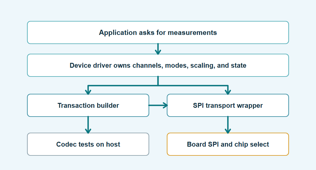
The public API is where the driver decides what kind of device it is exposing. If the API exposes byte buffers, every caller has to learn part of the protocol. If it exposes measurements, channels, ranges, modes, and status, the protocol can change without dragging the application along.
That matters after the first board revision. A second ADC may use a different command byte, a replacement sensor may move a status flag, or the same part may land on another SPI instance. A measurement-oriented API keeps those changes inside the driver instead of spreading into acquisition, logging, filtering, and calibration code.
The public API is the part of the driver the rest of the firmware will live with. If it exposes command bytes, register addresses, dummy clocks, or raw transfer buffers, the application slowly becomes part of the driver, and every later chip change gets more expensive.
For an ADC, application code usually wants samples, channels, ranges, and status. For a temperature sensor, it wants degrees, raw readings, or a refresh result. For an accelerometer, it wants axes, data-ready flags, and maybe interrupt configuration. The code below shows that public boundary: status values, typed result structures, an opaque chip handle, and functions that talk in device concepts instead of SPI bytes.
|
1 2 3 4 5 6 7 8 9 10 11 12 13 14 15 16 17 18 19 20 21 22 23 24 25 26 27 28 29 30 31 32 33 34 |
/* ChipStatus is the small error vocabulary shared by driver and application code. */ typedef enum { ChipStatus_Ok = 0, ChipStatus_BusError, ChipStatus_Timeout, ChipStatus_BadId, ChipStatus_BadParameter, ChipStatus_NotReady, ChipStatus_DataInvalid } ChipStatus; /* AdcSample is a decoded measurement, not a raw SPI response buffer. */ typedef struct { int32_t microvolts; bool overrange; } AdcSample; /* TemperatureSample keeps the value and freshness information together. */ typedef struct { int32_t milli_celsius; uint32_t timestamp_ms; } TemperatureSample; /* The application sees an opaque handle, not the driver's private fields. */ typedef struct SpiChip SpiChip; /* Public functions expose device operations instead of command bytes. */ ChipStatus adc_read_channel(SpiChip *chip, uint8_t channel, AdcSample *out); ChipStatus sensor_read_temperature(SpiChip *chip, TemperatureSample *out); ChipStatus chip_read_id(SpiChip *chip, uint8_t *out_id); ChipStatus chip_configure_low_power(SpiChip *chip, bool enable); |
If your codebase has both I2C and SPI chip drivers, keep this status vocabulary consistent. The transport-specific details should stay below the driver boundary, but callers should not have to learn one enum for I2C timeouts, another enum for SPI timeouts, and a third convention for bad IDs. Shared names such as ChipStatus_BusError, ChipStatus_Timeout, ChipStatus_BadId, ChipStatus_NotReady, and ChipStatus_DataInvalid make logging, retries, and integration tests easier to reuse.
The caller should not have to remember that register 0x00 is a device ID, that the read bit is bit 7, or that a conversion result needs two dummy bytes before valid data appears. Those rules belong inside the driver.
Keep the SPI transport replaceable
This separation solves two practical problems at once. It lets you test command bytes and decode logic before hardware is ready, and it lets the same device driver move between board support packages without carrying one vendor HAL through every helper.
Lesson learned: Drivers that call the MCU HAL directly often look faster to write, but they become expensive when the board changes. A simple GPIO chip select change, an RTOS migration, or a move from blocking transfers to DMA can force edits across the whole driver. A small transport wrapper keeps that churn in one place.
SPI drivers become easier to test when they do not call the MCU vendor HAL from every helper. Wrap the board-specific transfer once, then pass it into the driver. The snippet below shows a small transport table, a driver object that stores it, and an attach function that rejects incomplete board bindings before the driver is used. It also leaves room for STM32 board code to provide a short cycle-based or timer-based delay, and for AURIX board code to satisfy chip-select timing through QSPI hardware configuration.
|
1 2 3 4 5 6 7 8 9 10 11 12 13 14 15 16 17 18 19 20 21 22 23 24 25 26 27 28 29 30 31 32 33 34 35 36 37 38 39 40 41 42 43 44 45 46 47 48 49 50 |
/* SpiBusOps is the replaceable boundary between chip logic and board SPI code. */ typedef struct { ChipStatus (*select)(void *user); ChipStatus (*transfer)(void *user, const uint8_t *tx, uint8_t *rx, size_t length); ChipStatus (*deselect)(void *user); void (*delay_us)(void *user, uint32_t us); /* * Optional: use this when the board transport can really honor nanosecond * timing. STM32 code might implement this with a timer or cycle counter. * AURIX QSPI code might instead satisfy CS delays in the controller setup * and leave this hook unused. */ void (*delay_ns)(void *user, uint32_t ns); uint32_t (*time_ms)(void *user); void *user; } SpiBusOps; /* SpiChip stores the transport binding and the datasheet profile for one device. */ struct SpiChip { SpiBusOps bus; SpiChipProfile profile; bool initialized; }; /* Attach validates the board hooks before any transfer can use them. */ ChipStatus spi_chip_attach(SpiChip *chip, const SpiBusOps *bus, const SpiChipProfile *profile) { if ((chip == NULL) || (bus == NULL) || (profile == NULL)) { return ChipStatus_BadParameter; } if ((bus->select == NULL) || (bus->transfer == NULL) || (bus->deselect == NULL) || (bus->delay_us == NULL) || (bus->time_ms == NULL)) { return ChipStatus_BadParameter; } chip->bus = *bus; chip->profile = *profile; chip->initialized = false; return ChipStatus_Ok; } |
This is not an abstraction for its own sake. It pays for itself when you can test the register encoding without hardware, and when a second board uses the same chip with a different chip-select GPIO or SPI peripheral.
Understand the actual SPI transaction
This is where many off-by-one receive bugs begin. SPI receive data is aligned with clocked bytes, not with the meaning you wish the transaction had. If the command byte clocks in an ignored byte, every response index after that has to account for the ignored byte.
When this is not explicit, engineers often fix the symptom in the decoder by shifting indexes until the bench reading looks right. That creates fragile code. The next register read, burst transfer, or device variant may need a different number of dummy bytes, and the hidden assumption breaks again.
SPI is full duplex, even when the device protocol feels half duplex. Every byte transmitted by the controller clocks in one byte from the device. Those early receive bytes may be meaningless, old conversion data, status, or the first part of the payload. The datasheet decides, not the SPI peripheral.
The transfer helper should own chip select and should return the first real error it sees. It should also make sure chip select is released when a transfer fails. The code below shows that policy in one place: use the board’s nanosecond delay hook when it exists, fall back to conservative microsecond rounding only when the underlying STM32, AURIX, or board-support layer needs a microsecond API, assert chip select, transfer the frame, hold chip select long enough, and preserve the transfer error if cleanup also has a problem.
|
1 2 3 4 5 6 7 8 9 10 11 12 13 14 15 16 17 18 19 20 21 22 23 24 25 26 27 28 29 30 31 32 33 34 35 36 37 38 39 40 41 42 43 44 45 46 47 48 49 50 51 52 53 54 55 56 57 58 59 60 61 62 63 64 65 66 67 68 69 70 71 72 73 74 |
#define SPI_NS_PER_US 1000u #define SPI_NS_TO_US_CEIL_BIAS 999u /* * Fallback only: convert nanosecond timing to whole microseconds when the * underlying board support layer only provides a microsecond delay API. */ static uint32_t spi_delay_ns_to_us_ceil(uint16_t delay_ns) { /* * Integer division truncates. Adding 999 before dividing by 1000 implements * ceil(delay_ns / 1000) without floating point or a branch. */ return (delay_ns + SPI_NS_TO_US_CEIL_BIAS) / SPI_NS_PER_US; } /* spi_chip_delay_ns keeps the policy choice in the board-facing layer. */ static void spi_chip_delay_ns(SpiChip *chip, uint16_t delay_ns) { if (delay_ns == 0u) { return; } if (chip->bus.delay_ns != NULL) { /* Good: keep sub-microsecond CS timing when the platform supports it. */ chip->bus.delay_ns(chip->bus.user, delay_ns); return; } /* * Fallback: if the platform only exposes microsecond waits, round up so the * driver never violates the datasheet minimum. This may wait longer than an * STM32 timer/DWT path or an AURIX hardware-QSPI timing path. */ chip->bus.delay_us(chip->bus.user, spi_delay_ns_to_us_ceil(delay_ns)); } /* spi_chip_transfer owns chip select timing for one complete SPI frame. */ static ChipStatus spi_chip_transfer(SpiChip *chip, const uint8_t *tx, uint8_t *rx, size_t length) { if ((chip == NULL) || (length == 0u)) { return ChipStatus_BadParameter; } /* Good: select is the board layer's chance to apply SPI mode and speed. */ ChipStatus status = chip->bus.select(chip->bus.user); if (status != ChipStatus_Ok) { return status; } spi_chip_delay_ns(chip, chip->profile.timing.cs_setup_ns); status = chip->bus.transfer(chip->bus.user, tx, rx, length); spi_chip_delay_ns(chip, chip->profile.timing.cs_hold_ns); /* Good: release chip select even if the transfer failed. */ ChipStatus deselect_status = chip->bus.deselect(chip->bus.user); /* Good: honor the minimum inactive time so an immediate next transfer cannot violate the profile's cs_inactive_ns requirement. */ spi_chip_delay_ns(chip, chip->profile.timing.cs_inactive_ns); if (status != ChipStatus_Ok) { return status; } return deselect_status; } |
A failed transfer should remain the primary diagnostic. The helper still releases chip select, but a deselect problem after a bad transfer should not hide the transfer error that explains the transaction failure. If the transfer succeeds and deselect is the first failing operation, returning the deselect status is reasonable.
This helper is intentionally ordinary. You want one place where chip select behavior is consistent, not five clever variations that each fail a little differently.
Build register access in one place
Centralizing register command construction is less about saving lines and more about preventing quiet disagreement. One helper may set the read bit as bit 7 while another assumes bit 6 is the burst bit. The code still compiles, and it may even pass a simple ID read, until a multi-byte transfer or write-back path exposes the mismatch.
The maintenance benefit is reviewability. When a new engineer checks the driver against the datasheet, there is one helper to compare against the command format instead of a dozen local byte expressions spread across unrelated functions.
Many SPI sensors and mixed-signal chips use a simple register interface, but the register format is not universal. Some use bit 7 as the read bit, some use bit 6 as a multi-byte flag, some auto-increment addresses, and some require address and data phases in separate chip-select windows.
The driver should turn those rules into helper functions. For a reusable driver, command-format masks belong in the chip profile, so the helper applies behavior names instead of hard-coding bit positions inside transfer code. The snippet below shows named frame indexes, one command builder, and a single-register read that deliberately ignores the first received byte because it was clocked during the command phase.
|
1 2 3 4 5 6 7 8 9 10 11 12 13 14 15 16 17 18 19 20 21 22 23 24 25 26 27 28 29 30 31 32 33 34 35 36 37 38 39 40 41 42 43 44 45 46 47 48 49 50 51 52 53 54 55 |
/* Named indexes make the two-byte register read frame reviewable. */ enum { SPI_REGISTER_READ_FRAME_LEN = 2u, SPI_REGISTER_RX_VALUE_INDEX = 1u, SPI_REGISTER_DUMMY_BYTE = 0x00u }; /* make_register_command centralizes address masking, read bits, and burst bits. */ static uint8_t make_register_command(const SpiChip *chip, uint8_t address, bool read, bool burst) { uint8_t command = address; uint8_t address_mask = (uint8_t)((1u << chip->profile.register_address_bits) - 1u); command &= address_mask; if (read) { /* Good: read behavior is represented by the profile's named mask. */ command |= chip->profile.read_bit_mask; } if (burst && chip->profile.has_auto_increment_bit) { /* Good: auto-increment behavior is represented by one named mask. */ command |= chip->profile.auto_increment_mask; } return command; } /* chip_read_register performs one command byte plus one dummy byte for clocks. */ ChipStatus chip_read_register(SpiChip *chip, uint8_t address, uint8_t *value) { if ((chip == NULL) || (value == NULL)) { return ChipStatus_BadParameter; } uint8_t tx[SPI_REGISTER_READ_FRAME_LEN] = { make_register_command(chip, address, true, false), SPI_REGISTER_DUMMY_BYTE }; uint8_t rx[SPI_REGISTER_READ_FRAME_LEN] = {0}; ChipStatus status = spi_chip_transfer(chip, tx, rx, sizeof(tx)); if (status != ChipStatus_Ok) { return status; } /* Good: the first received byte is ignored because it was clocked during the command byte. */ *value = rx[SPI_REGISTER_RX_VALUE_INDEX]; return ChipStatus_Ok; } |
The single-register read above passes false for burst because it does not need auto-increment. Page 2 uses the same command helper for multi-byte reads where the chip must advance through consecutive registers.
There are devices where this helper is too simple. That is fine. The point is not to force every device into one universal helper. The point is to avoid rewriting command-byte rules in five unrelated functions.
Do not hide device identity checks
An identity check is cheap insurance. It catches wrong chip variants, assembly mistakes, chip-select routing errors, reset problems, and SPI mode mistakes before the driver starts writing configuration registers. Even when an ID read is not complete proof, it gives bring-up a clear first question.
Field note: On mixed boards, it is easy to talk to the wrong chip-select line and still see plausible MISO activity because another device is sharing the bus. A specific ID failure is much more useful than a later report that temperature is always zero or the ADC range configuration did not stick.
A device ID register is not a complete hardware validation, but it is a useful early check. If the driver cannot read the expected ID, stop and return a specific error. Do not let the rest of initialization continue with a random register map. The example below keeps the register address and expected value at the definition boundary, then turns an unexpected response into ChipStatus_BadId instead of a vague initialization failure.
|
1 2 3 4 5 6 7 8 9 10 11 12 13 14 15 16 17 18 19 20 21 22 23 24 |
/* Device identity values live at the datasheet definition boundary. */ #define TEMP_SENSOR_REG_ID 0x00u #define TEMP_SENSOR_EXPECTED_ID 0x5Au /* temp_sensor_init proves the selected chip before configuration writes begin. */ ChipStatus temp_sensor_init(SpiChip *chip) { uint8_t id = 0u; ChipStatus status = chip_read_register(chip, TEMP_SENSOR_REG_ID, &id); if (status != ChipStatus_Ok) { return status; } if (id != TEMP_SENSOR_EXPECTED_ID) { /* Good: wrong part, wrong mode, or wrong wiring gets a distinct result. */ return ChipStatus_BadId; } chip->initialized = true; return ChipStatus_Ok; } |
If a chip has no ID register, use a harmless readback register, a reset value, or a configuration write and readback if the datasheet allows it. If none of those exist, say so in the driver comments and in the bring-up checklist. Silence here wastes bench time.
Keep command style separate from register style
This is where generic driver layers often become too clever. A command-driven ADC is not a register device just because it uses SPI. Forcing it into a register abstraction hides timing and bit layout, and the code becomes harder to compare with the datasheet.
The practical rule is to model the device as it is. Register helpers are excellent for register-mapped sensors. Command builders are better for converters that encode channel selection, start bits, and dummy clocks directly in the transfer. Mixing those two styles without naming the difference is a common source of review mistakes.
Not every SPI chip is register based. Some ADCs, especially small external ADCs, use command fields that are clocked directly into the converter. A typical pattern is a start bit, single-ended or differential selection, channel selection, and dummy clocks while the result comes back. The code below keeps that command style separate from the register helper by using named command bits, named byte indexes, and one builder for the ADC frame.
|
1 2 3 4 5 6 7 8 9 10 11 12 13 14 15 16 17 18 19 20 21 22 23 24 25 26 27 28 29 30 31 32 33 34 35 36 37 38 39 40 41 42 43 44 45 46 47 48 49 50 51 52 53 54 55 56 57 58 59 60 61 62 63 64 65 66 67 68 |
/* These command bits describe this ADC-style frame, not a register address. */ #define MCP_STYLE_START_BIT 0x04u #define MCP_STYLE_SINGLE_ENDED 0x02u #define MCP_STYLE_CHANNEL_HIGH_BIT_MASK 0x01u #define MCP_STYLE_RESULT_HIGH_MASK 0x0Fu #define MCP_STYLE_DUMMY_BYTE 0x00u /* Frame indexes and shifts keep command encoding and response decoding aligned. */ enum { MCP_STYLE_FRAME_LEN = 3u, MCP_STYLE_COMMAND_INDEX = 0u, MCP_STYLE_CHANNEL_INDEX = 1u, MCP_STYLE_DUMMY_INDEX = 2u, MCP_STYLE_RX_HIGH_INDEX = 1u, MCP_STYLE_RX_LOW_INDEX = 2u, MCP_STYLE_CHANNEL_HIGH_SHIFT = 2u, MCP_STYLE_CHANNEL_LOW_SHIFT = 6u, MCP_STYLE_RESULT_SHIFT = 8u, MCP_STYLE_MAX_CHANNEL = 7u }; /* build_adc_command encodes channel selection for a command-driven ADC. */ static ChipStatus build_adc_command(uint8_t channel, uint8_t tx[MCP_STYLE_FRAME_LEN]) { if ((tx == NULL) || (channel > MCP_STYLE_MAX_CHANNEL)) { return ChipStatus_BadParameter; } tx[MCP_STYLE_COMMAND_INDEX] = MCP_STYLE_START_BIT | MCP_STYLE_SINGLE_ENDED | (uint8_t)((channel >> MCP_STYLE_CHANNEL_HIGH_SHIFT) & MCP_STYLE_CHANNEL_HIGH_BIT_MASK); tx[MCP_STYLE_CHANNEL_INDEX] = (uint8_t)(channel << MCP_STYLE_CHANNEL_LOW_SHIFT); tx[MCP_STYLE_DUMMY_INDEX] = MCP_STYLE_DUMMY_BYTE; return ChipStatus_Ok; } /* adc_read_raw_12bit sends the command frame and extracts the 12-bit payload. */ ChipStatus adc_read_raw_12bit(SpiChip *chip, uint8_t channel, uint16_t *out_raw) { uint8_t tx[MCP_STYLE_FRAME_LEN] = {0}; uint8_t rx[MCP_STYLE_FRAME_LEN] = {0}; if ((chip == NULL) || (out_raw == NULL)) { return ChipStatus_BadParameter; } ChipStatus status = build_adc_command(channel, tx); if (status != ChipStatus_Ok) { return status; } status = spi_chip_transfer(chip, tx, rx, sizeof(tx)); if (status != ChipStatus_Ok) { return status; } /* Good: mask reserved bits before returning a raw conversion result. */ *out_raw = (uint16_t)(((uint16_t)(rx[MCP_STYLE_RX_HIGH_INDEX] & MCP_STYLE_RESULT_HIGH_MASK) << MCP_STYLE_RESULT_SHIFT) | rx[MCP_STYLE_RX_LOW_INDEX]); return ChipStatus_Ok; } |
That example is shaped like common 12-bit SPI ADCs. The details must still come from the actual device datasheet. The useful habit is to separate "build command" from "decode result" so each part can be tested by itself.
At this point the driver has a shape: a public API, a replaceable SPI transport, a transaction helper, register access helpers, ID checks, and command builders for devices that are not register mapped. Page 2 moves into the behavior that usually makes normal SPI chips tricky: conversion timing, burst reads, stale data, data decoding, status flags, DMA, and shared bus use.