
The first I2C driver for a new chip often starts with one register read. Send the device address, send the register address, read a byte, and the bench suddenly looks friendly. Then the same code fails after reset, works only at 100 kHz, reads the wrong register after a mode change, hangs when a sensor stretches the clock, or splits a register read into two transactions because the HAL function looked convenient. That is where an I2C driver stops being a wrapper around bus calls and starts becoming firmware that owns a datasheet contract.
This guide is about ordinary I2C chips: temperature sensors, pressure sensors, accelerometers, ADCs, DACs, EEPROMs, GPIO expanders, power monitors, front-end devices, and small measurement chips. The examples stay with normal embedded peripherals where the hard work is address handling, register-pointer behavior, repeated-start transactions, timing, ACK/NACK handling, data decoding, recovery, and hardware bring-up.
Guide to this reference
This guide is split into three pages so it can be used as a reference instead of one long scroll.
- Page 1, datasheet to driver shape. Start here for I2C address rules, register-pointer behavior, public API design, transport boundaries, combined transactions, and identity checks.
- Page 2, sensors, EEPROMs, and runtime behavior. Use this page for conversion timing, NACK polling, raw data decoding, block reads, error categories, shared bus rules, DMA, and asynchronous flow.
- Page 3, testing, bring-up, and long-term maintenance. Finish here for fake transports, logic-analyzer checks, stuck-bus recovery, calibration, scratch-buffer ownership, and the final checklist.
Page 1 builds the driver skeleton first. The later pages assume you have separated the application API from the I2C transaction details, because that separation makes every later decision easier to test and easier to review.
Key patterns for Page 1
- Keep one address representation at the driver boundary, normally the 7-bit I2C target address.
- Treat register-pointer writes and repeated-start reads as one transaction, not two casual bus calls.
- Put chip-specific register, command, timing, and identity rules inside the driver.
- Keep the board transport replaceable so host tests can check transaction shape before hardware exists.
What this guide covers
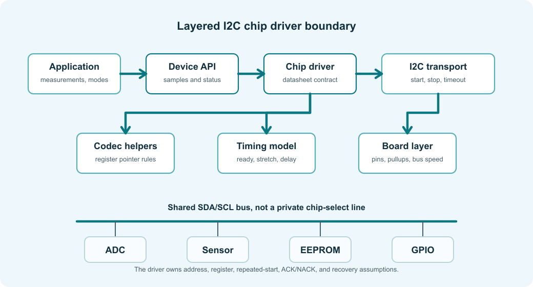
The idea running through the whole article is ownership. A useful I2C driver carries the details the rest of the firmware should not have to remember: 7-bit address handling, repeated-start reads, temporary NACKs during write cycles, auto-increment rules, and the final-byte NACK before STOP. When those rules live in one driver boundary, callers can ask for device behavior instead of replaying the datasheet at every call site.
In practice, the first version of an I2C driver is usually written under bring-up pressure. That is exactly when it is easiest to accept a shortcut that works for one board, one bus speed, and one register read. The sections below are meant to keep those shortcuts from becoming the permanent interface.
Most I2C driver mistakes are not caused by misunderstanding that I2C has SDA and SCL. They happen because the driver does not capture the exact contract of the chip. A temperature sensor might require a command write, a conversion delay, and then a read. An EEPROM might NACK while it is internally writing a page. A GPIO expander might use address pins that change the low bits of the 7-bit address. An ADC might return status flags in the same bytes as conversion data.
This guide focuses on the parts that make those details manageable:
- Reading the datasheet as a driver contract.
- Choosing a public API that does not leak register bytes into application code.
- Keeping the I2C transport replaceable for host tests and board ports.
- Building combined write-read transactions in one place.
- Handling repeated starts, ACK/NACK behavior, and register pointer state.
- Modeling conversion timing, EEPROM write cycles, and stale data.
- Decoding raw measurements without burying assumptions in callers.
- Sharing the bus across chips with different speeds and timing needs.
- Debugging with logic-analyzer captures and fake transports.
- Keeping the driver useful across board revisions and chip variants.
The examples are written in C because C still fits many small MCU projects, but the structure maps cleanly to C++, Rust, Zephyr, ESP-IDF, Linux userspace tools, or a project-specific hardware abstraction layer. If your project also has SPI peripherals, the companion guide Writing Drivers for SPI Chips in Embedded Systems applies the same driver architecture to SPI-specific chip contracts.
Common chip shapes and gotchas
Different I2C chips fail in different ways. A pattern that is perfect for a small register-map sensor can be the wrong shape for an EEPROM or a command-driven ADC. Before writing the public API, classify the chip and name the datasheet rule that someone is most likely to forget.
| Chip style | Practical driver gotcha |
|---|---|
| TMP117-style temperature sensors | Temperature data is easy to read, but configuration, conversion mode, data-ready behavior, and device ID checks still belong in the driver. |
| BME280-style environmental sensors | The register reads are not the hard part. Calibration registers, compensation formulas, oversampling, and mode transitions are the long-term maintenance risk. |
| 24AA256-style EEPROMs | Page boundaries and write-cycle ACK polling matter more than the simple byte read path. A driver that ignores page limits can wrap writes inside the EEPROM page. |
| ADS1115-style ADCs | Channel, gain, data rate, and conversion mode are configuration state. A single-shot read should not assume the conversion register already contains a fresh result. |
| GPIO expanders | Direction, pull-up, polarity, output latch, interrupt flag, and interrupt capture registers often need a clear ownership model or the application will fight the driver. |
The examples above are common shapes, not promises about every device in a family. The useful habit is to classify the hard part early, before chip knowledge starts leaking into application code through a supposedly generic I2C wrapper.
Read the datasheet as a driver contract
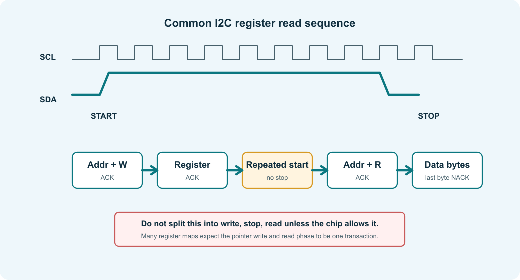
I2C gives you a bus protocol, not a device protocol. The bus defines START, STOP, addressing, ACK/NACK, arbitration, and the timing relationship between SDA and SCL. The chip datasheet decides what an address means, whether a register pointer exists, how many bytes are in that pointer, whether the pointer auto-increments, whether a repeated start is required, and how long a conversion or internal write cycle can take.
Field note: A common bring-up failure is a driver that works with a quick register read but fails once the acquisition task starts. The root cause is often a hidden transaction assumption. The code writes a register pointer, sends STOP, then performs a separate read. The chip expected a repeated start, so the register pointer changed, expired, or was interpreted differently. The bus looks active, the address ACKs, and yet the data is wrong.
A good I2C driver starts with a small checklist, not with code. Before writing the first function, pull out the details that affect every transaction. For a normal peripheral chip, that usually means:
- 7-bit target address, including any address pins or board straps.
- Whether the datasheet shows addresses as 7-bit values or 8-bit address-plus-R/W bytes.
- Maximum bus speed, and whether the chip supports Standard-mode, Fast-mode, Fast-mode Plus, or High-speed mode.
- Whether the target may stretch SCL and whether the controller driver supports that.
- Register pointer width, often 0, 1, or 2 bytes.
- Register pointer byte order for 16-bit register maps.
- Whether register reads require a repeated start.
- Whether multi-byte reads auto-increment the register pointer.
- Reset delay, first valid measurement timing, and conversion delay.
- Busy, data-ready, overflow, or invalid-data flags.
- EEPROM or flash-style write cycle behavior, including ACK polling.
- Whether the bus can be shared safely with other chips at the chosen speed and pull-up values.
This is where many drivers start drifting. A helper called “read register” may really need to write a pointer, issue a repeated start, read two bytes, NACK the final byte, and then send STOP. A delay that looks safely fixed at 10 ms may depend on oversampling, and an address written as 0x90 may be the 8-bit write byte from a table rather than the 7-bit address expected by the MCU HAL.
The practical way to keep this under control is to put the assumptions into a driver profile. It does not need to copy the datasheet into C, but it should hold the values that can change between chips, boards, modes, and transport implementations.
The snippet below shows a compact profile shape for an I2C chip. Notice how the bus timing, 7-bit address, register-pointer format, repeated-start rule, reset delay, and conversion timeout are all named before any transfer code uses them.
|
1 2 3 4 5 6 7 8 9 10 11 12 13 14 15 16 17 18 19 20 21 22 23 24 25 26 27 28 29 30 31 32 33 34 35 36 37 38 39 |
/* Note: Bus timing describes controller-level limits shared by this chip. */ typedef struct { uint32_t bus_hz; uint32_t transaction_timeout_ms; bool target_may_stretch_clock; } I2cBusTiming; /* Note: The chip profile gathers datasheet and board assumptions in one place. */ typedef struct { I2cBusTiming timing; uint8_t address_7bit; uint8_t register_address_bytes; bool register_address_big_endian; bool read_requires_repeated_start; bool register_pointer_auto_increments; uint32_t reset_delay_ms; uint32_t conversion_timeout_ms; } I2cChipProfile; /* Good: the datasheet and board assumptions are explicit and reviewable. */ static const I2cChipProfile temperature_sensor_profile = { .timing = { .bus_hz = 400000u, .transaction_timeout_ms = 20u, .target_may_stretch_clock = true, }, /* Note: 0x48 is the 7-bit address, not the shifted 8-bit write byte. */ .address_7bit = 0x48u, .register_address_bytes = 1u, .register_address_big_endian = true, /* Good: repeated-start behavior is a profile rule, not a caller habit. */ .read_requires_repeated_start = true, .register_pointer_auto_increments = true, .reset_delay_ms = 2u, .conversion_timeout_ms = 150u, }; |
The exact values above are example values, not a replacement for a datasheet. The point is the shape. If the driver has a profile, you can review what the chip expects before you read the bus code.
Datasheets do not always present I2C addresses the same way. Some show a 7-bit target address such as 0x48. Others show the 8-bit write and read bytes, such as 0x90 and 0x91. Many MCU HALs expect the 7-bit address, while some older APIs expect the shifted address byte. Pick one representation at the driver boundary, name it clearly, and convert only at the board transport boundary if needed.
Choose the public API before the bus code
The public API is where the driver decides what kind of device it is exposing. If the API talks in register addresses and byte buffers, each caller has to learn part of the datasheet. If it talks in measurements, channels, ranges, modes, flags, and status, the protocol can change without dragging callers along.
That boundary matters after the first board revision. A replacement temperature sensor may move the data-ready bit, a new ADC may use a command sequence instead of a register pointer, or the same EEPROM may be strapped to a different address. With a device-oriented API, those changes stay in the driver rather than spreading into acquisition, logging, filtering, calibration, and UI code.
For an ADC, application code usually wants samples, channels, ranges, and validity flags. For a temperature sensor, it wants degrees, raw readings, or a refresh result. For an EEPROM, it wants bounded reads and writes with clear write-cycle behavior. The I2C details are implementation details.
The next snippet shows the application-facing side of that boundary. It defines a shared status vocabulary, sample structs with named units, and function prototypes that talk about device operations instead of I2C bytes.
|
1 2 3 4 5 6 7 8 9 10 11 12 13 14 15 16 17 18 19 20 21 22 23 24 25 26 27 28 29 30 31 32 33 34 35 36 37 38 |
/* Note: One driver status vocabulary keeps HAL-specific errors out of callers. */ typedef enum { ChipStatus_Ok = 0, ChipStatus_BusError, ChipStatus_AddressNack, ChipStatus_DataNack, ChipStatus_Timeout, ChipStatus_BusStuck, ChipStatus_BadId, ChipStatus_BadParameter, ChipStatus_NotReady, ChipStatus_DataInvalid } ChipStatus; /* Note: Application-facing samples use named units and validity flags. */ typedef struct { int32_t microvolts; bool overrange; bool fresh; } AdcSample; typedef struct { int32_t milli_celsius; uint32_t timestamp_ms; bool valid; } TemperatureSample; /* Note: Callers hold an opaque chip handle instead of bus internals. */ typedef struct I2cChip I2cChip; /* Good: APIs describe device behavior, not I2C transactions. */ ChipStatus adc_read_channel(I2cChip *chip, uint8_t channel, AdcSample *out); ChipStatus sensor_read_temperature(I2cChip *chip, TemperatureSample *out); ChipStatus eeprom_read_bytes(I2cChip *chip, uint16_t offset, uint8_t *out, size_t length); ChipStatus chip_read_id(I2cChip *chip, uint8_t *out_id); |
The caller should not have to remember that register 0x00 is a device ID, that a two-byte register pointer is big endian, or that the final byte of an I2C read should be NACKed. Those rules belong inside the driver and transport.
Keep the I2C transport replaceable
This separation solves two practical problems at once. It lets you test address use, pointer encoding, repeated-start behavior, and decode logic before hardware is ready, and it lets the same chip driver move between board support packages without carrying one vendor HAL through every helper.
Lesson learned: Drivers that call the MCU HAL directly from every helper often look faster to write, but they become expensive when the board changes. A move from blocking transfers to an RTOS bus driver, a controller that expects shifted addresses, or a target that needs bus recovery can force edits across the whole driver. A small transport wrapper keeps that churn in one place.
I2C drivers become easier to test when the transport exposes the operations the device protocol actually needs. For register devices, that usually includes a combined write-read operation so the driver can request a repeated start as one logical transaction.
In the snippet below, the transport table is the small adapter between portable chip code and board-specific I2C code. Its key operation is write_read, because a repeated-start register read should be requested as one logical transaction rather than assembled from two unrelated calls.
|
1 2 3 4 5 6 7 8 9 10 11 12 13 14 15 16 17 18 19 20 21 22 23 24 25 26 27 28 29 30 31 32 33 34 35 36 37 38 39 40 41 42 43 44 45 46 47 48 49 50 51 52 53 54 55 56 57 58 59 60 |
/* Note: The transport table is the seam between chip protocol and board I2C code. */ typedef struct { ChipStatus (*write)(void *user, uint8_t address_7bit, const uint8_t *data, size_t length, uint32_t timeout_ms); ChipStatus (*read)(void *user, uint8_t address_7bit, uint8_t *data, size_t length, uint32_t timeout_ms); /* Good: combined write-read lets the driver request a repeated start explicitly. */ ChipStatus (*write_read)(void *user, uint8_t address_7bit, const uint8_t *write_data, size_t write_length, uint8_t *read_data, size_t read_length, uint32_t timeout_ms); ChipStatus (*recover_bus)(void *user); void (*delay_ms)(void *user, uint32_t ms); uint32_t (*time_ms)(void *user); /* Note: user points at the board bus object, RTOS bus manager, or fake test bus. */ void *user; } I2cBusOps; /* Note: The chip object binds transport, profile, and driver-owned state. */ struct I2cChip { I2cBusOps bus; I2cChipProfile profile; bool initialized; }; /* Note: Attach validates the transport before any helper can use it. */ ChipStatus i2c_chip_attach(I2cChip *chip, const I2cBusOps *bus, const I2cChipProfile *profile) { if ((chip == NULL) || (bus == NULL) || (profile == NULL)) { return ChipStatus_BadParameter; } if ((bus->write == NULL) || (bus->read == NULL) || (bus->write_read == NULL) || (bus->delay_ms == NULL) || (bus->time_ms == NULL)) { return ChipStatus_BadParameter; } chip->bus = *bus; chip->profile = *profile; chip->initialized = false; return ChipStatus_Ok; } |
This is not an abstraction for its own sake. It pays for itself when a host test can prove that a register read used a combined transaction, and when a second board uses the same chip through a different controller driver.
A minimal driver object is enough for the first examples, but reusable drivers usually need a little runtime state. Keep that state about the chip and its communication contract. Sampling policy, UI state, alarm behavior, and product decisions belong above this layer.
The short snippet below expands the chip object with runtime state. It shows which details belong inside the driver object and which policy decisions should stay outside it.
|
1 2 3 4 5 6 7 8 9 10 11 12 13 14 15 16 17 18 19 |
/* Note: Runtime state records what this driver has learned from the chip. */ typedef struct { bool initialized; bool powered; uint16_t observed_device_id; uint8_t observed_revision; uint32_t last_success_ms; } I2cChipState; /* Good: the driver object owns chip state, not application policy. */ /* Note: this replaces the minimal object above; later snippets use chip->state. */ struct I2cChip { I2cBusOps bus; I2cChipProfile profile; I2cChipState state; }; |
This is also a good place to store discovered chip revision or feature bits. If a later silicon revision changes a status mask, conversion delay, or calibration layout, the driver can select the right profile after reading the ID register instead of pushing revision checks into callers.
The recover_bus callback is optional in the structure above because some systems cannot safely recover the bus from a chip driver. On a simple single-controller board, bus recovery may live in the board transport. On a shared RTOS system, recovery may need coordination at a higher level so one driver does not toggle SCL while another transaction is in progress.
Understand the actual I2C transaction
This is where many broken register reads begin. I2C devices often use a register pointer: the controller writes the register address first, then reads data from that pointer. Many chips expect those phases to be joined by a repeated start, not separated by a STOP that changes the meaning of the next read.
When this is not explicit, engineers often fix the symptom in the decoder by changing indexes, adding delays, or rereading until the value looks plausible. That creates fragile code. The next register, burst read, or device variant may need a different transaction shape, and the hidden assumption breaks again.
A driver helper should own the register-pointer encoding and the transaction shape. It should also keep the 7-bit address separate from the R/W bit. The board transport can shift or adapt that address if a vendor HAL needs a different representation.
The following code snippet shows the register-pointer helper and the public register-read wrapper. It centralizes one-byte versus two-byte pointer encoding, byte order, argument checks, and the combined write-read transaction.
|
1 2 3 4 5 6 7 8 9 10 11 12 13 14 15 16 17 18 19 20 21 22 23 24 25 26 27 28 29 30 31 32 33 34 35 36 37 38 39 40 41 42 43 44 45 46 47 48 49 50 51 52 53 54 55 56 57 58 59 60 61 62 63 64 65 66 67 |
/* Note: This helper supports one-byte and two-byte register pointers. */ enum { I2C_MAX_REGISTER_ADDRESS_BYTES = 2u }; /* Note: Pointer encoding lives in one helper so endian bugs stay local. */ static ChipStatus build_register_pointer(const I2cChip *chip, uint16_t reg, uint8_t *out, size_t *out_len) { if ((chip == NULL) || (out == NULL) || (out_len == NULL)) { return ChipStatus_BadParameter; } if (chip->profile.register_address_bytes == 1u) { out[0] = (uint8_t)reg; *out_len = 1u; return ChipStatus_Ok; } if (chip->profile.register_address_bytes == 2u) { if (chip->profile.register_address_big_endian) { out[0] = (uint8_t)(reg >> 8); out[1] = (uint8_t)reg; } else { out[0] = (uint8_t)reg; out[1] = (uint8_t)(reg >> 8); } *out_len = 2u; return ChipStatus_Ok; } return ChipStatus_BadParameter; } /* Note: declared here, defined in the next snippet, so this wrapper can call it. */ static ChipStatus i2c_chip_write_read(I2cChip *chip, const uint8_t *write_data, size_t write_length, uint8_t *read_data, size_t read_length); /* Note: Public register reads are small wrappers around pointer build plus write-read. */ ChipStatus i2c_chip_read_registers(I2cChip *chip, uint16_t reg, uint8_t *out, size_t length) { uint8_t pointer[I2C_MAX_REGISTER_ADDRESS_BYTES]; size_t pointer_len = 0u; if ((chip == NULL) || (out == NULL) || (length == 0u)) { return ChipStatus_BadParameter; } ChipStatus status = build_register_pointer(chip, reg, pointer, &pointer_len); if (status != ChipStatus_Ok) { return status; } /* Good: this requests one combined transaction with a repeated start. */ return i2c_chip_write_read(chip, pointer, pointer_len, out, length); } |
A small chip-level helper can also centralize validation, timeout use, and optional bus recovery. Keep it conservative: repeated retries can hide a real protocol mistake, while one controlled recovery attempt after a stuck bus can be useful on simple boards.
The next helper shows the lower-level combined transaction wrapper. It validates buffers, uses the profile timeout, and performs exactly one controlled recovery retry when the board layer reports a stuck bus.
|
1 2 3 4 5 6 7 8 9 10 11 12 13 14 15 16 17 18 19 20 21 22 23 24 25 26 27 28 29 30 31 32 33 34 35 36 37 38 39 40 41 42 43 44 45 46 47 48 49 50 51 52 53 |
/* Note: This helper validates buffers, applies the chip timeout, and owns recovery policy. */ static ChipStatus i2c_chip_write_read(I2cChip *chip, const uint8_t *write_data, size_t write_length, uint8_t *read_data, size_t read_length) { if (chip == NULL) { return ChipStatus_BadParameter; } if ((write_length > 0u) && (write_data == NULL)) { return ChipStatus_BadParameter; } if ((read_length > 0u) && (read_data == NULL)) { return ChipStatus_BadParameter; } if ((write_length == 0u) && (read_length == 0u)) { return ChipStatus_BadParameter; } /* Good: the 7-bit address and timeout come from the chip profile. */ ChipStatus status = chip->bus.write_read(chip->bus.user, chip->profile.address_7bit, write_data, write_length, read_data, read_length, chip->profile.timing.transaction_timeout_ms); if ((status == ChipStatus_BusStuck) && (chip->bus.recover_bus != NULL)) { ChipStatus recovery = chip->bus.recover_bus(chip->bus.user); if (recovery != ChipStatus_Ok) { return recovery; } // Good: retry once after physical bus recovery, not forever. status = chip->bus.write_read(chip->bus.user, chip->profile.address_7bit, write_data, write_length, read_data, read_length, chip->profile.timing.transaction_timeout_ms); } return status; } |
The helper is not a replacement for a bus manager. If the bus is shared across tasks, drivers, or processors, the transport still needs to serialize complete transactions and decide where recovery is allowed.
The helper above looks ordinary, and that is intentional. The important decision is that pointer encoding and combined write-read behavior live in one place, so callers do not build pointer bytes or guess whether this chip needs a repeated start.
Do not hide device identity checks
A device ID or reset-value check is not a luxury. It catches wrong addresses, soldering mistakes, board strap mistakes, swapped parts, and accidental bus conflicts early. The check does not need to run before every transaction, but initialization should prove that the expected chip responded before the driver starts returning measurements.
Not every I2C chip has a useful identity register. Some simple EEPROMs and GPIO expanders do not. In that case, use a reset-value register, a harmless configuration readback, or a small smoke test that proves the expected behavior without changing outputs unexpectedly.
The initialization snippet below shows a simple identity check. It waits for reset timing, reads the ID register through the shared helper, and fails early if the expected device is not present.
|
1 2 3 4 5 6 7 8 9 10 11 12 13 14 15 16 17 18 19 20 21 22 23 24 25 26 27 28 29 30 31 32 33 34 35 |
/* Note: Named constants keep datasheet register values out of transaction logic. */ enum { TEMP_SENSOR_ID_REGISTER = 0x0Fu, TEMP_SENSOR_EXPECTED_ID = 0x5Au }; /* Note: Initialization proves the expected device is present before samples are trusted. */ ChipStatus temperature_sensor_init(I2cChip *chip) { if (chip == NULL) { return ChipStatus_BadParameter; } chip->bus.delay_ms(chip->bus.user, chip->profile.reset_delay_ms); uint8_t id = 0u; ChipStatus status = i2c_chip_read_registers(chip, TEMP_SENSOR_ID_REGISTER, &id, sizeof(id)); if (status != ChipStatus_Ok) { return status; } /* Good: a wrong chip or wrong address fails before data is trusted. */ if (id != TEMP_SENSOR_EXPECTED_ID) { return ChipStatus_BadId; } chip->state.initialized = true; return ChipStatus_Ok; } |
The ID value above is an example value. In real code, use the value and register name from the datasheet. If the chip has multiple silicon revisions, record which IDs are accepted and why.
Keep register style separate from command style
Not every I2C chip is a simple register map. Some sensors use command words, some ADCs need a command write followed by conversion time and a read, and EEPROMs add page boundaries plus write-cycle polling. If all of those are forced into one generic read_register helper, odd flags and exceptions eventually leak into callers.
Use the helper shape that matches the chip. Register-map devices deserve register helpers, command devices deserve command helpers, and EEPROM-like devices deserve memory helpers that understand page limits and write polling. They can share the same transport, status type, and timeout policy without pretending every device speaks the same protocol.
The following snippet shows a command-style chip path. Instead of inventing a fake register address, the driver sends the command bytes directly through the same transport vocabulary.
|
1 2 3 4 5 6 7 8 9 10 11 12 13 14 15 16 17 18 19 20 21 22 23 24 25 26 27 28 29 |
/* Note: A command device may send command bytes instead of a register pointer. */ typedef struct { uint8_t msb; uint8_t lsb; } SensorCommand; /* Note: This function starts the chip operation but does not pretend to read a register. */ ChipStatus command_sensor_start_measurement(I2cChip *chip, SensorCommand command) { if (chip == NULL) { return ChipStatus_BadParameter; } uint8_t tx[] = { command.msb, command.lsb, }; /* Good: command-style devices do not need a fake register address. */ return chip->bus.write(chip->bus.user, chip->profile.address_7bit, tx, sizeof(tx), chip->profile.timing.transaction_timeout_ms); } |
The driver boundary should reflect the chip’s real protocol. A clean command helper is much easier to review than a register helper filled with magic values that are not really registers.
By the end of this first page, the driver has the important shape: a device-oriented API, an explicit chip profile, a replaceable transport, a central register or command codec, and a clear initialization path. Page 2 uses that shape to handle the runtime behavior that usually causes I2C bugs on real boards.