
Part 2 of 3
Key patterns for Page 2
- Treat conversion time, EEPROM write time, and freshness as part of the driver contract.
- Prefer ready flags, interrupt state, or ACK polling when the device provides them.
- Decode raw bytes once, with named byte order, status bits, scaling, and validity rules.
- Use blocking calls, state machines, callbacks, or RTOS queues deliberately instead of hiding long waits inside innocent function names.
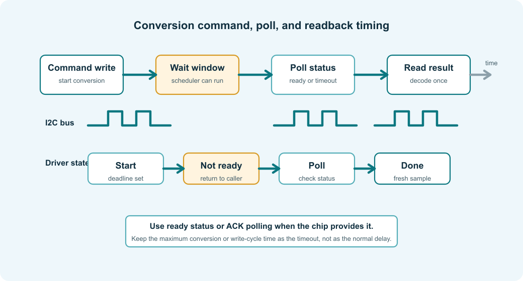
Model the conversion sequence
Many I2C chips do not return a fresh measurement just because a register was read. A sensor may need a start-conversion command, an ADC may need channel selection plus acquisition and conversion time, and a power monitor may update periodically while exposing flags that tell you whether the value is fresh.
The driver should make that sequence visible. A blocking helper can be practical in small firmware, but it should still name the start, wait, read, and decode phases. When a conversion delay is hidden inside a function that looks like a plain register read, watchdog behavior, scheduler latency, and measurement freshness become much harder to review.
The snippet below introduces a cooperative read job. It names the start, wait, read, decode, done, and failed states so conversion timing is visible to the scheduler and to reviewers.
|
1 2 3 4 5 6 7 8 9 10 11 12 13 14 15 16 17 18 19 20 21 22 23 24 25 26 27 28 29 30 |
/* Note: The state machine names each protocol phase for async or cooperative use. */ typedef enum { SensorSeq_Idle = 0, SensorSeq_Start, SensorSeq_WaitReady, SensorSeq_Read, SensorSeq_Decode, SensorSeq_Done, SensorSeq_Failed } SensorReadState; /* Note: The job object stores progress between scheduler calls. */ typedef struct { SensorReadState state; uint32_t deadline_ms; uint8_t raw[4]; ChipStatus result; } SensorReadJob; /* Note: Start only initializes state and deadline; later steps do the bus work. */ void sensor_read_job_start(I2cChip *chip, SensorReadJob *job, uint32_t now_ms) { (void)chip; job->state = SensorSeq_Start; job->deadline_ms = now_ms + 150u; job->result = ChipStatus_NotReady; } |
The setup above does not start the bus transaction yet. It gives the scheduler a concrete state object that can move one step at a time. That is useful in RTOS tasks, cooperative loops, and low-power firmware where the MCU should sleep between conversion phases.
Poll status instead of guessing delays
Fixed delays are sometimes necessary, but they should not be the first choice when the chip provides a better signal. A ready bit, interrupt pin, status register, or ACK polling loop usually gives better behavior across temperature, voltage, bus speed, and chip variants.
EEPROM write cycles are a good example. After a page write, many EEPROMs NACK their address while the internal write is busy. A fixed maximum delay works, but it slows every write to the worst case. ACK polling finishes as soon as the device is ready, while still enforcing a timeout.
The next snippet shows ACK polling for EEPROM-style write cycles. It treats address NACK as a temporary busy indication, but still returns other errors immediately and enforces a timeout.
|
1 2 3 4 5 6 7 8 9 10 11 12 13 14 15 16 17 18 19 20 21 22 23 24 25 26 27 28 29 30 31 32 33 34 |
/* Note: ACK polling treats address NACK as a temporary busy signal until timeout. */ ChipStatus i2c_wait_until_address_acks(I2cChip *chip, uint32_t timeout_ms) { if (chip == NULL) { return ChipStatus_BadParameter; } /* Note: Use elapsed time so tick wrap can be handled by unsigned subtraction. */ const uint32_t start_ms = chip->bus.time_ms(chip->bus.user); while ((chip->bus.time_ms(chip->bus.user) - start_ms) < timeout_ms) { ChipStatus status = chip->bus.write(chip->bus.user, chip->profile.address_7bit, NULL, 0u, chip->profile.timing.transaction_timeout_ms); if (status == ChipStatus_Ok) { return ChipStatus_Ok; } /* Good: address NACK can be a busy signal for EEPROM-style writes. */ if (status != ChipStatus_AddressNack) { return status; } chip->bus.delay_ms(chip->bus.user, 1u); } return ChipStatus_Timeout; } |
The key detail is not the exact polling interval. The key detail is that the code treats an expected busy NACK differently from a real bus failure. Arbitration loss, a stuck bus, or a controller timeout should not be buried under the idea that the chip is simply still busy.
For sensors and ADCs, the same idea often appears as a status register poll. If the datasheet gives both a maximum conversion delay and a ready bit, use the ready bit with the maximum delay as a timeout. That gives the normal path good latency and still prevents an infinite wait when the board is wrong.
Decode raw data in the driver
Raw bytes are not measurements yet. They still carry byte order, sign representation, alignment, scaling, status bits, and sometimes validity flags. If every caller decodes those bytes independently, the project can end up with several slightly different versions of the same measurement.
The driver should return a value in a named unit, or at least return a decoded raw count with clear validity flags. That keeps calibration, filtering, logging, and alarm code from learning the byte layout of the chip.
The following code snippet shows where raw bytes become a temperature sample. It names the byte indexes, owns the endian conversion, and returns milli-Celsius rather than exposing the register layout to callers.
|
1 2 3 4 5 6 7 8 9 10 11 12 13 14 15 16 17 18 19 20 21 22 23 24 25 26 27 28 29 30 31 32 33 34 35 36 37 38 39 40 41 42 |
/* Note: Byte indexes and scaling are named at the decode boundary. */ enum { TEMP_VALUE_REGISTER = 0x00u, TEMP_RAW_MSB_INDEX = 0u, TEMP_RAW_LSB_INDEX = 1u, TEMP_RAW_LENGTH = 2u, TEMP_LSB_MC = 125u }; /* Note: This decoder owns endian and signed-conversion details. */ static int16_t decode_signed_be16(const uint8_t *raw) { uint16_t word = ((uint16_t)raw[TEMP_RAW_MSB_INDEX] << 8) | (uint16_t)raw[TEMP_RAW_LSB_INDEX]; return (int16_t)word; } /* Note: The read function returns engineering units, not raw register bytes. */ ChipStatus temperature_sensor_read(I2cChip *chip, TemperatureSample *out) { uint8_t raw[TEMP_RAW_LENGTH]; if ((chip == NULL) || (out == NULL)) { return ChipStatus_BadParameter; } ChipStatus status = i2c_chip_read_registers(chip, TEMP_VALUE_REGISTER, raw, sizeof(raw)); if (status != ChipStatus_Ok) { return status; } int16_t counts = decode_signed_be16(raw); /* Good: callers receive a named unit instead of chip byte layout. */ out->milli_celsius = (int32_t)counts * TEMP_LSB_MC; out->timestamp_ms = chip->bus.time_ms(chip->bus.user); out->valid = true; return ChipStatus_Ok; } |
The register address in the example is intentionally small, but in real code it should be a named constant from the datasheet. If the chip packs status flags into the same bytes as the measurement, decode the flags before scaling and return them through the result structure.
Handle block reads deliberately
Multi-byte I2C reads can be safer than several single-byte reads, but only when the chip supports the behavior you are relying on. Some chips auto-increment the register pointer, some latch a coherent snapshot when the first byte is read, and some update high and low bytes independently unless a specific sequence is followed.
That shows up in accelerometers, power monitors, counters, ADC result registers, and almost any measurement wider than one byte. Separate high-byte and low-byte transactions can combine two different samples, while an unsupported block read can repeat one register or wander into reserved space.
Put the block-read rule into the driver profile or into a chip-specific helper. Do not let callers decide whether a burst read is safe.
The block-read snippet below shows a coherent multi-byte sample. It checks that the profile supports auto-increment, reads all axis bytes in one transfer, and decodes each little-endian pair at a named offset.
|
1 2 3 4 5 6 7 8 9 10 11 12 13 14 15 16 17 18 19 20 21 22 23 24 25 26 27 28 29 30 31 32 33 34 35 36 37 38 39 40 41 42 43 44 45 46 47 48 49 50 51 52 53 |
/* Note: The first register and burst length describe one coherent XYZ sample. */ enum { ACCEL_FIRST_AXIS_REGISTER = 0x28u, ACCEL_X_LSB_INDEX = 0u, ACCEL_Y_LSB_INDEX = 2u, ACCEL_Z_LSB_INDEX = 4u, ACCEL_AXIS_RAW_BYTES = 6u }; /* Note: Counts are decoded but not yet calibrated into physical units. */ typedef struct { int16_t x_counts; int16_t y_counts; int16_t z_counts; } AccelRawSample; /* Note: The helper makes little-endian byte pairs explicit at each axis offset. */ static int16_t decode_le16_at(const uint8_t *raw, size_t index) { uint16_t word = (uint16_t)raw[index] | ((uint16_t)raw[index + 1u] << 8); return (int16_t)word; } ChipStatus accel_read_xyz(I2cChip *chip, AccelRawSample *out) { uint8_t raw[ACCEL_AXIS_RAW_BYTES]; if ((chip == NULL) || (out == NULL)) { return ChipStatus_BadParameter; } /* Good: reject burst reads when this chip profile cannot auto-increment. */ if (!chip->profile.register_pointer_auto_increments) { return ChipStatus_BadParameter; } ChipStatus status = i2c_chip_read_registers(chip, ACCEL_FIRST_AXIS_REGISTER, raw, sizeof(raw)); if (status != ChipStatus_Ok) { return status; } out->x_counts = decode_le16_at(raw, ACCEL_X_LSB_INDEX); out->y_counts = decode_le16_at(raw, ACCEL_Y_LSB_INDEX); out->z_counts = decode_le16_at(raw, ACCEL_Z_LSB_INDEX); return ChipStatus_Ok; } |
The profile check may look strict, but it documents the assumption. If a device variant needs a special burst bit or a snapshot command, add a chip-specific path instead of making every caller remember the exception.
Preserve error categories
A single generic bus error is not enough for a driver that will be debugged on real hardware. Address NACK, data NACK, timeout, arbitration loss, a stuck bus, a bad ID, invalid data, and not-ready status all point to different fixes.
That distinction matters during bring-up. Address NACK sends you toward power, reset, soldering, address pins, or the address format. Data NACK during a pointer write suggests an invalid register, the wrong transaction shape, or a busy device. Timeout and stuck-bus errors point more toward electrical problems, clock stretching support, a crashed target, or a controller that needs recovery.
A transport wrapper should translate vendor HAL errors into the driver's status vocabulary once. After that, the chip driver can make useful decisions without depending on one HAL's enum names.
The next snippet shows the transport error mapping layer. It converts board-driver results into the driver status enum once, so chip code does not depend on vendor-specific error names.
|
1 2 3 4 5 6 7 8 9 10 11 12 13 14 15 16 17 18 19 20 21 |
/* Note: Translate board-driver results once at the transport boundary. */ static ChipStatus map_board_i2c_error(BoardI2cResult result) { switch (result) { case BoardI2cResult_Ok: return ChipStatus_Ok; case BoardI2cResult_AddressNack: return ChipStatus_AddressNack; case BoardI2cResult_DataNack: return ChipStatus_DataNack; case BoardI2cResult_Timeout: return ChipStatus_Timeout; case BoardI2cResult_BusStuck: return ChipStatus_BusStuck; default: return ChipStatus_BusError; } } |
The driver does not need to expose every possible controller fault to the application, but it should preserve the failures that change the recovery decision. Retrying address NACK during EEPROM write polling can be correct. Retrying a stuck bus forever is usually not.
Share the I2C bus carefully
I2C is physically shared. The same two wires may connect the MCU, sensors, EEPROM, GPIO expanders, power monitors, level shifters, connectors, and test pads. That makes board-level assumptions part of the software problem, even when the chip driver is nicely written.
The driver should not choose pull-up resistor values, but it should not ignore the consequences either. Weak pull-ups, too much bus capacitance, a level shifter with poor edges, or a target that stretches SCL beyond the controller timeout can look like random software failures. The board transport owns the electrical setup, but the chip profile should record speed and timeout requirements so the bus manager can configure the controller correctly.
On RTOS systems, the bus also needs serialization. A repeated-start register read is one transaction, not a write call that can be interrupted by another driver's read call. The transport or bus manager should hold the bus lock across the combined operation.
The snippet below shows a locked shared-bus transfer. It holds the bus lock across the whole combined transaction and applies the active bus speed before the board driver starts the transfer.
|
1 2 3 4 5 6 7 8 9 10 11 12 13 14 15 16 17 18 19 20 21 22 23 24 25 26 27 28 29 30 31 32 |
/* Note: The board layer serializes the shared bus around the whole combined transaction. */ ChipStatus board_i2c_write_read_locked(BoardI2c *bus, uint8_t address_7bit, const uint8_t *tx, size_t tx_len, uint8_t *rx, size_t rx_len, uint32_t timeout_ms) { if (bus == NULL) { return ChipStatus_BadParameter; } /* Good: no other target can split the register-pointer write from the read phase. */ board_mutex_lock(&bus->lock); /* Good: the bus speed is applied for this device before the transaction. */ board_i2c_set_speed(bus, bus->active_bus_hz); BoardI2cResult result = board_i2c_write_read(bus, address_7bit, tx, tx_len, rx, rx_len, timeout_ms); board_mutex_unlock(&bus->lock); return map_board_i2c_error(result); } |
The example assumes the board layer already knows the active speed for the selected device. Some projects set the speed once for the whole bus. That is fine when all devices and the board layout support it. If one device requires 100 kHz and another is happy at 400 kHz, record that explicitly instead of letting whichever driver initialized last decide the controller speed.
Use DMA when the transaction is large enough
Most I2C transactions are short. A register pointer plus two data bytes usually does not deserve DMA, because setup cost, buffer lifetime rules, interrupt handling, and cache maintenance can be larger than the transfer itself.
DMA begins to make sense for larger EEPROM transfers, display updates, camera control blocks, long sensor FIFO reads, or systems where the CPU has useful work to do while the bus is active. Even there, buffer ownership has to be explicit, because starting DMA from a stack buffer that goes out of scope is a classic failure that only appears under load.
Use a threshold and keep DMA policy in the transport or a clearly named async path. The chip driver can request a block read, but the board transport usually knows whether the controller, memory region, and RTOS integration make DMA worthwhile.
The small helper below shows one way to keep DMA policy out of chip logic. It uses a named threshold so small register reads stay simple while larger transfers can use a board-specific DMA path.
|
1 2 3 4 5 6 7 8 9 10 11 12 13 14 15 16 |
/* Note: The threshold documents where DMA starts to pay for this board. */ enum { I2C_DMA_MIN_TRANSFER_BYTES = 32u }; /* Note: DMA selection belongs in the board transport, not every chip helper. */ bool board_i2c_should_use_dma(size_t write_len, size_t read_len) { size_t total_len = write_len + read_len; /* Tradeoff: small register reads are clearer and often faster without DMA. */ return total_len >= I2C_DMA_MIN_TRANSFER_BYTES; } |
This threshold is not universal. Measure it on the target if performance matters. On a small MCU, DMA may save CPU time but add interrupt latency, cache rules, or memory placement requirements. On a larger RTOS system, the controller driver may already make that decision for you.
Keep asynchronous operation explicit
Hidden blocking looks harmless until the system grows. A helper named like a normal read can hide a conversion delay, EEPROM write-cycle polling, repeated retries, or a long bus timeout, and that cost lands in watchdog servicing, control-loop timing, UI responsiveness, and power management.
For slow sensors, high resolution ADCs, EEPROM writes, and periodic acquisition, an explicit state machine is often clearer than a blocking function with hidden delays. The state machine can start conversion, return to the scheduler, poll readiness later, and read the result when it is available.
There are three common ways to expose that work. None is automatically the best choice:
- State machines fit cooperative firmware and simple RTOS tasks. They are easy to inspect, easy to unit test, and make timeouts explicit.
- Callbacks fit controller drivers that already signal completion from an interrupt or DMA path. Keep callback work short and move decoding to task context when it can block or allocate.
- RTOS queues or futures fit larger systems where one bus worker owns I2C transactions. They make bus ownership clear, but they add queue lifetime and cancellation rules.
For small bare-metal firmware, a state machine is often the easiest first async shape. For Zephyr, Linux, or a project with a shared bus worker, a queued request may match the system better. The important part is that the caller can see whether the operation may wait, retry, or complete later.
The state-machine snippet below shows how an asynchronous read advances through protocol phases. Each call does a small amount of work and returns the current result instead of hiding a long wait inside a blocking read.
|
1 2 3 4 5 6 7 8 9 10 11 12 13 14 15 16 17 18 19 20 21 22 23 24 25 26 27 28 29 30 31 32 33 34 35 36 37 38 39 40 41 42 43 44 45 46 47 48 49 50 51 |
enum { SENSOR_MEASURE_COMMAND_MSB = 0x24u, SENSOR_MEASURE_COMMAND_LSB = 0x00u }; /* Note: The step function advances one protocol phase per scheduler call. */ ChipStatus sensor_read_job_step(I2cChip *chip, SensorReadJob *job) { switch (job->state) { case SensorSeq_Start: /* Note: the named command bytes form the measurement command word for this chip. */ job->result = command_sensor_start_measurement(chip, (SensorCommand){ .msb = SENSOR_MEASURE_COMMAND_MSB, .lsb = SENSOR_MEASURE_COMMAND_LSB }); job->state = (job->result == ChipStatus_Ok) ? SensorSeq_WaitReady : SensorSeq_Failed; break; case SensorSeq_WaitReady: /* Good: timeout is checked before polling so the state machine cannot wait forever. */ if (chip->bus.time_ms(chip->bus.user) > job->deadline_ms) { job->result = ChipStatus_Timeout; job->state = SensorSeq_Failed; break; } job->result = sensor_check_ready(chip); if (job->result == ChipStatus_Ok) { job->state = SensorSeq_Read; } break; case SensorSeq_Read: job->result = sensor_read_raw_measurement(chip, job->raw, sizeof(job->raw)); job->state = (job->result == ChipStatus_Ok) ? SensorSeq_Decode : SensorSeq_Failed; break; case SensorSeq_Decode: job->state = SensorSeq_Done; job->result = ChipStatus_Ok; break; default: break; } return job->result; } |
The value of this pattern is not style. It makes watchdog behavior, scheduler latency, and acquisition timing visible during review. Blocking reads can still be a practical choice in a simple system, but their cost should be visible in the function name, documentation, or call site.
By the end of this second page, the driver can handle the runtime behavior of ordinary I2C peripherals: conversion timing, ACK polling, data decoding, block reads, shared buses, DMA thresholds, and asynchronous operation. Page 3 turns that into something you can bring up on hardware, test on a host, and maintain across board revisions.