
Part 2 of 3
Previously: We set up the driver boundary, SPI transaction shape, register helpers, ID checks, and command-style ADC access.
In this part: We handle conversion timing, polling, decoding, burst reads, shared buses, DMA thresholds, and asynchronous reads.
Key patterns for Page 2
- Treat conversion timing, freshness, status flags, and stale samples as driver behavior, not caller folklore.
- Decode raw bytes once, with named byte order, sign handling, alignment, status bits, and validity rules.
- Use burst reads only when the chip guarantees coherent data or the driver explicitly handles snapshot rules.
- Choose blocking, polling, DMA, callbacks, or state machines deliberately, with buffer ownership visible.
Model the conversion sequence
A conversion sequence is state, even in a small blocking driver. Configuration is applied at one moment, conversion begins at another, data is not ready for a while, and the read phase only becomes meaningful after that. Naming those moments prevents stale data from looking like a valid measurement.
The failure mode is usually subtle. The driver returns numbers, the numbers change, and the system appears alive. Only later does someone notice that a channel change is one sample late, or that the first sample after changing gain is invalid. Modeling the sequence gives you a place to discard or flag those cases intentionally.
ADCs and sensors often have a measurement sequence that is separate from the SPI read. Some parts continuously convert, some require a start command, some need a delay before readout, some return the previous conversion while starting the next one, and some expose readiness through a status bit or interrupt pin.
If the driver treats all of those chips as read register and return value, stale or half-ready data will eventually look like a real sample.
The driver should make the sequence explicit. A blocking version is fine for small systems when the conversion time is short and known. A nonblocking version is better when the conversion time is long, when the system has a watchdog, or when the part is sampled periodically. The snippet below shows the job object that carries a conversion request through those phases without hiding the wait inside a blocking read.
|
1 2 3 4 5 6 7 8 9 10 11 12 13 14 15 16 17 18 19 20 21 22 23 24 25 26 27 28 29 30 31 32 33 34 35 36 37 38 |
/* AdcSeqState names each visible phase of one non-blocking conversion. */ typedef enum { AdcSeq_Idle = 0, AdcSeq_Start, AdcSeq_WaitReady, AdcSeq_Read, AdcSeq_Decode, AdcSeq_Done, AdcSeq_Failed } AdcSeqState; /* AdcReadJob carries request state between scheduler ticks or task iterations. */ typedef struct { AdcSeqState state; uint8_t channel; /* Note: start plus timeout, so elapsed-time checks survive tick wrap. */ uint32_t start_ms; uint32_t timeout_ms; uint16_t raw; ChipStatus result; } AdcReadJob; /* adc_read_job_start initializes the job but does not touch the SPI bus yet. */ void adc_read_job_start(AdcReadJob *job, uint8_t channel, uint32_t now_ms, uint32_t timeout_ms) { job->state = AdcSeq_Start; job->channel = channel; job->start_ms = now_ms; job->timeout_ms = timeout_ms; job->raw = 0u; job->result = ChipStatus_NotReady; } |
The blocking helper can sit on top of the same sequence if that fits the project. What matters is that the code names the waiting step and the timeout.
Poll status instead of guessing delays
Polling exists because conversion time is often a function of configuration. Oversampling, filter settings, power mode, reference settling, and sensor temperature can all move the ready time, so a fixed delay that looked safe in the lab may be too short in a cold chamber or unnecessarily long during normal operation.
There is a balance here. Polling too aggressively can waste bus bandwidth and CPU time, especially on a shared bus. A good driver uses the ready flag when available, waits at a reasonable interval, and still keeps a timeout so a broken device does not trap the system forever.
Some parts also specify a minimum poll interval. Polling faster than that can contend with the device’s internal measurement or register-update path, so the poll delay should be named from the datasheet instead of treated as an arbitrary sleep.
Fixed delays are tempting because they make the first bench demo quick, but they age poorly. Temperature, supply voltage, oversampling, filter settings, and part revisions can all change conversion timing. If the chip provides a data-ready flag, busy bit, or data-ready pin, use it with a timeout as the guard. The code below shows a simple polling helper with named status bits, a named poll interval, and a timeout that keeps a missing ready flag from becoming an infinite wait.
|
1 2 3 4 5 6 7 8 9 10 11 12 13 14 15 16 17 18 19 20 21 22 23 24 25 26 27 28 |
/* Status register values are named at the datasheet boundary. */ #define SENSOR_REG_STATUS 0x03u #define SENSOR_STATUS_DATA_READY (1u << 0) #define SENSOR_READY_POLL_DELAY_US 100u /* sensor_wait_data_ready polls readiness while preserving bus and timeout errors. */ ChipStatus sensor_wait_data_ready(SpiChip *chip, uint32_t timeout_ms) { uint32_t start = chip->bus.time_ms(chip->bus.user); while ((chip->bus.time_ms(chip->bus.user) - start) < timeout_ms) { uint8_t status_reg = 0u; ChipStatus status = chip_read_register(chip, SENSOR_REG_STATUS, &status_reg); if (status != ChipStatus_Ok) { return status; } if ((status_reg & SENSOR_STATUS_DATA_READY) != 0u) { return ChipStatus_Ok; } chip->bus.delay_us(chip->bus.user, SENSOR_READY_POLL_DELAY_US); } return ChipStatus_Timeout; } |
There are chips where a fixed delay is the only option. In that case, keep the delay named, keep it close to the datasheet value, and avoid hiding it deep inside a function called read().
Decode raw data in the driver
Raw decoding belongs close to the transaction because that is where the byte order, alignment, status bits, and sign rules are still visible. If each caller decodes raw bytes independently, the project can end up with two definitions of the same measurement.
Lesson learned: One of the most common ADC bugs is a value that is correct near zero and wrong near full scale because sign extension or masking was done in the wrong order. Keeping the decoder small and isolated makes it easy to test those edge values without running the whole firmware.
Raw SPI bytes are not the same thing as a measurement. Many devices return left-aligned values, status bits, sign bits, two's complement values, or multi-byte big-endian fields. The snippet below keeps the bit masks and scaling formula together so callers do not repeat sign extension, reference scaling, or width assumptions in application code.
|
1 2 3 4 5 6 7 8 9 10 11 12 13 14 15 16 17 18 19 20 21 22 23 24 25 26 27 28 29 30 |
/* Masks name the raw ADC representation before scaling starts. */ #define ADC_12BIT_VALUE_MASK 0x0FFFu #define ADC_12BIT_SIGN_BIT_MASK 0x0800u #define ADC_12BIT_SIGN_EXTEND_MASK 0xF000u /* sign_extend_12bit converts a packed 12-bit result into a normal int16_t. */ static int16_t sign_extend_12bit(uint16_t raw) { raw &= ADC_12BIT_VALUE_MASK; if ((raw & ADC_12BIT_SIGN_BIT_MASK) != 0u) { /* Good: extend the sign bit before converting to a signed type. */ raw |= ADC_12BIT_SIGN_EXTEND_MASK; } return (int16_t)raw; } /* adc_counts_to_microvolts applies reference scaling after decoding sign. */ static int32_t adc_counts_to_microvolts(int16_t counts, int32_t reference_uv, uint8_t resolution_bits) { int32_t full_scale = (int32_t)(1u << (resolution_bits - 1u)); /* Good: use a wider type for the multiply before dividing. */ return (int32_t)(((int64_t)counts * reference_uv) / full_scale); } |
The application can still request raw data when it needs calibration or diagnostics. The default API should return values that are difficult to misuse.
Handle burst reads deliberately
Burst reads are attractive because they reduce overhead and can keep related fields together. They also rely on device-specific promises: address auto-increment, snapshot behavior, byte order, and sometimes a required read sequence. If one of those assumptions is wrong, the driver can return a mixture of old and new fields.
This is especially visible in motion sensors and environmental sensors. A single-axis read may work for weeks, then a later optimization changes it to a burst read and introduces occasional impossible vectors or pressure jumps. The burst helper should document what the device promises and what the driver assumes.
Sensors often support multi-byte burst reads for X, Y, Z axes or temperature, pressure, and humidity fields. Burst reads reduce overhead and keep fields coherent, but only when the chip supports auto-increment and when the register snapshot behavior is understood. The example below shows a burst helper with explicit register, frame, and payload indexes so byte order and receive offsets stay reviewable.
|
1 2 3 4 5 6 7 8 9 10 11 12 13 14 15 16 17 18 19 20 21 22 23 24 25 26 27 28 29 30 31 32 33 34 35 36 37 38 39 40 41 42 43 44 45 46 47 48 49 50 51 52 |
/* The burst starts at the first axis register in this sensor's map. */ #define SENSOR_REG_OUT_X_LSB 0x32u /* Named payload indexes make receive-byte offsets and byte order visible. */ enum { SENSOR_AXIS_COUNT = 3u, SENSOR_AXIS_X = 0u, SENSOR_AXIS_Y = 1u, SENSOR_AXIS_Z = 2u, SENSOR_XYZ_FRAME_LEN = 7u, SENSOR_XYZ_COMMAND_INDEX = 0u, SENSOR_X_LSB_INDEX = 1u, SENSOR_X_MSB_INDEX = 2u, SENSOR_Y_LSB_INDEX = 3u, SENSOR_Y_MSB_INDEX = 4u, SENSOR_Z_LSB_INDEX = 5u, SENSOR_Z_MSB_INDEX = 6u, SENSOR_FIELD_SHIFT = 8u }; /* sensor_read_xyz_raw performs one coherent burst read and decodes three axes. */ ChipStatus sensor_read_xyz_raw(SpiChip *chip, int16_t out_xyz[SENSOR_AXIS_COUNT]) { if ((chip == NULL) || (out_xyz == NULL)) { return ChipStatus_BadParameter; } uint8_t tx[SENSOR_XYZ_FRAME_LEN] = {0}; uint8_t rx[SENSOR_XYZ_FRAME_LEN] = {0}; tx[SENSOR_XYZ_COMMAND_INDEX] = make_register_command(chip, SENSOR_REG_OUT_X_LSB, true, true); ChipStatus status = spi_chip_transfer(chip, tx, rx, sizeof(tx)); if (status != ChipStatus_Ok) { return status; } /* Good: decode little-endian fields in one place. */ out_xyz[SENSOR_AXIS_X] = (int16_t)(((uint16_t)rx[SENSOR_X_MSB_INDEX] << SENSOR_FIELD_SHIFT) | rx[SENSOR_X_LSB_INDEX]); out_xyz[SENSOR_AXIS_Y] = (int16_t)(((uint16_t)rx[SENSOR_Y_MSB_INDEX] << SENSOR_FIELD_SHIFT) | rx[SENSOR_Y_LSB_INDEX]); out_xyz[SENSOR_AXIS_Z] = (int16_t)(((uint16_t)rx[SENSOR_Z_MSB_INDEX] << SENSOR_FIELD_SHIFT) | rx[SENSOR_Z_LSB_INDEX]); return ChipStatus_Ok; } |
Do not assume every chip snapshots all fields at the first byte of a burst. Some devices require a specific status read, a data latch, or a read order. That assumption belongs beside the burst helper, not in a caller that only sees decoded axes.
A few older accelerometers and sensors latch multi-byte data only when a particular high byte is read, not when the first byte of the burst begins. That detail changes which byte order and read sequence are safe, so it belongs in the driver next to the burst helper.
Preserve error categories
Error categories are not decoration. They decide what the rest of the system can do next: a bus error points toward wiring, DMA, or peripheral configuration, a timeout suggests a missing ready flag or dead device, and an overrange sample may be a valid measurement event rather than a broken bus.
When all of these collapse into one failure code, debugging becomes log archaeology. Engineers start adding prints around every call site because the driver threw away the useful information at the source. Keeping categories separate is one of the cheapest ways to reduce future bench time.
There is a big difference between an SPI bus error, a chip timeout, a bad device ID, an invalid parameter, and a data overrange condition. Collapsing them into false makes debugging much harder. The snippet below shows a small diagnostics object and one recorder function, which keeps error accounting consistent without mixing policy into every call site.
|
1 2 3 4 5 6 7 8 9 10 11 12 13 14 15 16 17 18 19 20 21 22 23 24 25 26 27 28 29 30 31 32 33 34 35 36 37 38 |
/* ChipDiagnostics is persistent driver state for later logs and health checks. */ typedef struct { uint32_t bus_errors; uint32_t timeouts; uint32_t bad_ids; uint32_t invalid_samples; /* Note: overrange is a valid measurement event, not a ChipStatus error, so the sample decoder counts it rather than chip_record_error. */ uint32_t overranges; } ChipDiagnostics; /* chip_record_error keeps diagnostic accounting in one place. */ static void chip_record_error(ChipDiagnostics *diag, ChipStatus status) { if (diag == NULL) { return; } switch (status) { case ChipStatus_BusError: diag->bus_errors++; break; case ChipStatus_Timeout: diag->timeouts++; break; case ChipStatus_BadId: diag->bad_ids++; break; case ChipStatus_DataInvalid: diag->invalid_samples++; break; default: break; } } |
These counters should be treated as diagnostic state. If they are touched from both an interrupt and a task, protect them with the same synchronization rules you use elsewhere. volatile does not make increments atomic.
Share the SPI bus carefully
Shared SPI buses fail in ways that can look unrelated to the driver being edited. A display update can leave the peripheral in another mode, a flash driver can change the clock divisor, or a sensor held in reset can pull MISO enough to corrupt another device. The driver cannot fix bad hardware, but it can make its own bus requirements explicit before every transaction.
The maintenance consequence is straightforward: every new device on the bus becomes less risky when each existing driver reapplies its own timing and mode. Without that habit, adding one harmless peripheral can break a measurement chip that nobody touched.
Multiple SPI chips can share MOSI, MISO, and SCLK, but they do not share timing assumptions. One chip might need mode 0 at 8 MHz. Another might need mode 3 at 1 MHz. Some chips release MISO cleanly when chip select is high. Some boards need pullups or series resistors because one device behaves poorly during reset.
The driver should not assume the bus is already configured correctly. The board transport can reconfigure the SPI peripheral before each transaction if needed. The code below keeps the board-owned SPI handle, chip-select GPIO, and timing together, then reapplies the device timing before asserting chip select.
|
1 2 3 4 5 6 7 8 9 10 11 12 13 14 15 16 17 18 19 20 21 22 23 24 25 26 27 28 |
/* BoardSpiDevice is board-owned state, not portable chip-driver logic. */ typedef struct { void *hal_spi; void *cs_gpio; SpiChipTiming timing; } BoardSpiDevice; /* board_spi_select prepares this device's bus mode before CS goes active. */ static ChipStatus board_spi_select(void *user) { BoardSpiDevice *dev = (BoardSpiDevice *)user; /* Good: configure mode and speed for this chip before asserting CS. */ board_spi_apply_timing(dev->hal_spi, &dev->timing); board_gpio_write(dev->cs_gpio, false); return ChipStatus_Ok; } /* board_spi_deselect releases only this device's chip-select line. */ static ChipStatus board_spi_deselect(void *user) { BoardSpiDevice *dev = (BoardSpiDevice *)user; board_gpio_write(dev->cs_gpio, true); return ChipStatus_Ok; } |
This is especially important in projects where an RTOS driver, bootloader, display library, or storage stack also uses the same SPI peripheral.
Use DMA when the transaction is large enough
DMA is an engineering tradeoff, not a badge of maturity. It reduces CPU involvement for long transfers, but it adds buffer lifetime rules, completion handling, interrupt interactions, and sometimes cache maintenance. For short register transfers, the simple blocking path is often easier to reason about and faster end to end.
Field note: A common migration bug appears when a driver is moved from blocking SPI to DMA and keeps using stack buffers. The transfer starts, the function returns, the stack frame is reused, and the DMA engine later transmits or receives garbage. A documented threshold and a board-level DMA wrapper make that class of bug much easier to avoid.
DMA is useful for long bursts, display transfers, high-rate ADC captures, and sensor FIFOs. It is not automatically better for a two-byte register read. DMA setup overhead, cache maintenance, buffer alignment, and completion synchronization can be more expensive than a short blocking transfer.
Use a threshold and document it. The snippet below keeps the DMA decision in the board transport, where buffer lifetime, cache maintenance, alignment, and completion rules can be enforced without leaking MCU-specific details into the chip driver.
|
1 2 3 4 5 6 7 8 9 10 11 12 13 14 15 16 17 18 19 20 21 22 |
/* Below this transfer size, DMA overhead is usually not worth the complexity. */ #define SPI_DMA_MIN_BYTES 32u /* board_spi_transfer chooses the board transfer path, not the chip decoder. */ ChipStatus board_spi_transfer(void *user, const uint8_t *tx, uint8_t *rx, size_t length) { BoardSpiDevice *dev = (BoardSpiDevice *)user; if (length >= SPI_DMA_MIN_BYTES) { /* Tradeoff: DMA helps long transfers but adds completion and cache rules. */ return board_spi_transfer_dma(dev, tx, rx, length); } /* Good: short register transfers stay simple and deterministic. */ return board_spi_transfer_blocking(dev, tx, rx, length); } |
If the MCU has data cache, DMA buffers may need alignment, cache clean before transmit, and cache invalidate after receive. That belongs in the board transport, not in every device driver.
On some MCUs, the simpler rule is to place DMA buffers in a non-cacheable SRAM region. That policy also belongs in the board transport or memory allocator, because the chip driver should not know which memory bank is safe for DMA.
Keep asynchronous operation explicit
Hidden blocking looks harmless until the system grows. A helper named like a normal read can hide a conversion delay, a retry loop, or a long DMA wait, and that cost lands in watchdog servicing, control-loop timing, UI responsiveness, and power management.
An explicit state machine makes the cost visible. It gives the scheduler a chance to run other work, gives the watchdog a predictable path, and gives diagnostics a state name when something stalls. That is much easier to maintain than a call stack stuck somewhere inside a sensor read.
For slow sensors, high resolution ADCs, and periodic acquisition, an asynchronous state machine is often clearer than a blocking function with hidden delays. The state machine can start conversion, return to the scheduler, poll readiness later, and read the result when it is available.
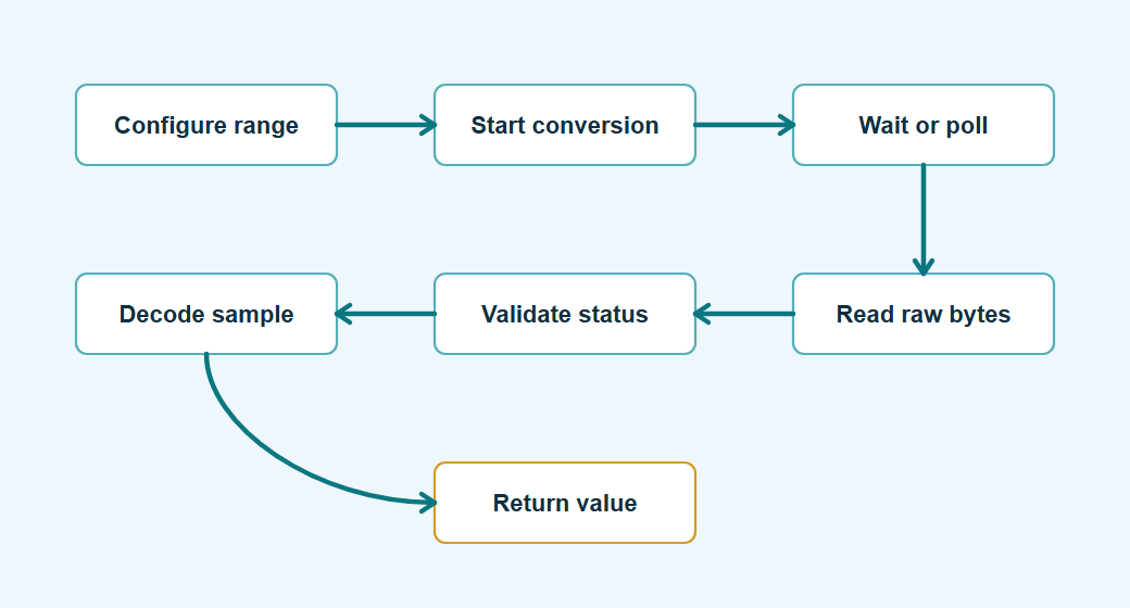
State machines and callbacks solve different parts of the problem. A state machine is a good driver-level shape when the chip has visible protocol phases: configure, start conversion, wait ready, read, decode, and report. It is easy to step in a cooperative loop, easy to unit test on a host, and easy to log when a job stalls in one named state.
Callbacks fit lower-level transfer completion. Many SPI controllers signal DMA completion or interrupt completion through a callback, but that callback should usually do the minimum work: record completion, wake a task, or advance a small scheduler flag. Decoding samples, applying calibration, retrying a failed conversion, or notifying application code is usually cleaner from task context, where the code can take locks, call time functions, and handle errors without ISR restrictions.
- Use a driver state machine when the chip protocol has wait windows, retries, polling, or multiple bus transactions per measurement.
- Use a transport callback when the SPI controller or DMA engine completes a single transfer asynchronously.
- Use an RTOS queue or future-like request object when multiple clients share one bus worker and the driver should not directly own scheduling.
The mistake to avoid is mixing these roles. A DMA completion callback that parses samples, updates shared measurement state, and calls application hooks is hard to test and easy to break with timing. A small callback plus explicit driver state gives the same non-blocking behavior with fewer hidden execution-context rules. The code below shows the step function for that state machine: each call advances at most one visible protocol phase and returns the current result.
|
1 2 3 4 5 6 7 8 9 10 11 12 13 14 15 16 17 18 19 20 21 22 23 24 25 26 27 28 29 30 31 32 33 34 35 36 37 38 39 40 41 42 43 44 45 46 47 |
/* adc_read_job_step advances one driver-level protocol state per call. */ ChipStatus adc_read_job_step(SpiChip *chip, AdcReadJob *job) { switch (job->state) { case AdcSeq_Start: job->result = adc_start_conversion(chip, job->channel); job->state = (job->result == ChipStatus_Ok) ? AdcSeq_WaitReady : AdcSeq_Failed; break; case AdcSeq_WaitReady: /* Good: unsigned elapsed-time comparison stays correct across tick wrap. */ if ((chip->bus.time_ms(chip->bus.user) - job->start_ms) >= job->timeout_ms) { job->result = ChipStatus_Timeout; job->state = AdcSeq_Failed; break; } job->result = adc_check_ready(chip); if (job->result == ChipStatus_Ok) { job->state = AdcSeq_Read; } else if (job->result != ChipStatus_NotReady) { /* Good: a bus failure fails the job now instead of spinning until timeout. */ job->state = AdcSeq_Failed; } break; case AdcSeq_Read: job->result = adc_read_raw_12bit(chip, job->channel, &job->raw); job->state = (job->result == ChipStatus_Ok) ? AdcSeq_Decode : AdcSeq_Failed; break; case AdcSeq_Decode: job->state = AdcSeq_Done; job->result = ChipStatus_Ok; break; default: break; } return job->result; } |
The value of this pattern is not style. It makes watchdog behavior, scheduler latency, and acquisition timing visible during review.
By the end of this second page, the driver can handle the runtime behavior of ordinary SPI peripherals: conversion timing, status polling, data decoding, burst reads, shared buses, DMA thresholds, and asynchronous operation. Page 3 turns that into something you can bring up on hardware, test on a host, and maintain across board revisions.