Part 3 of 3
Previously: We built the driver boundary, transaction helpers, timing model, data decoding, error handling, DMA choices, and async flow.
In this part: We focus on host tests, board bring-up, logic analyzer review, calibration, buffer ownership, and long-term driver boundaries.
Key patterns for Page 3
- Test command encoding, dummy-byte count, receive indexes, decoding, and error propagation before hardware.
- Use logic-analyzer captures to prove chip select, clock mode, MOSI bytes, MISO bytes, and deselect timing.
- Keep calibration, chip revision, diagnostic counters, and buffer ownership visible in the driver object.
- Let the board layer own GPIO mapping, SPI peripheral setup, DMA cache rules, and multi-device MISO behavior.
Test the codec without hardware
Host-side codec tests are valuable because they remove the board from the question. If a command byte is wrong in a host test, it will be wrong on the bench too, so catching it early keeps hardware debugging focused on hardware.
These tests also protect future edits. When someone adds a burst read, changes an address helper, or ports the driver to a different compiler, the tests catch protocol drift before it becomes a measurement bug.
The transaction builder and decoder should be testable without a board. This is the fastest way to catch wrong read bits, wrong byte order, wrong masks, and off-by-one receive indexes. The fake transport below records the transfer, compares the transmitted bytes, supplies a scripted response, and can inject failures so error paths are tested too.
|
1 2 3 4 5 6 7 8 9 10 11 12 13 14 15 16 17 18 19 20 21 22 23 24 25 26 27 28 29 30 31 32 33 34 35 36 37 38 39 40 41 42 43 44 |
/* FakeSpi scripts one expected transaction for host-side driver tests. */ typedef struct { uint8_t expected_tx[16]; uint8_t response_rx[16]; size_t expected_len; ChipStatus forced_status; size_t fail_on_transfer; size_t transfer_count; bool saw_expected_transfer; } FakeSpi; /* fake_transfer checks TX bytes, injects failures, and returns scripted RX bytes. */ static ChipStatus fake_transfer(void *user, const uint8_t *tx, uint8_t *rx, size_t length) { FakeSpi *fake = (FakeSpi *)user; fake->transfer_count++; /* Good: the fake can inject bus failures without changing driver code. */ if ((fake->forced_status != ChipStatus_Ok) && ((fake->fail_on_transfer == 0u) || (fake->transfer_count == fake->fail_on_transfer))) { return fake->forced_status; } if (length != fake->expected_len) { return ChipStatus_BusError; } for (size_t i = 0; i < length; ++i) { if (tx[i] != fake->expected_tx[i]) { return ChipStatus_BusError; } rx[i] = fake->response_rx[i]; } fake->saw_expected_transfer = true; return ChipStatus_Ok; } |
These tests do not prove the electrical interface. They prove that the driver sends and decodes the bytes it claims to send and decode, and that it preserves the error categories the rest of the firmware relies on. That is still a large part of the bug surface.
A useful host test set should include more than the happy path. At minimum, test the driver with:
- The expected command byte, dummy bytes, burst bit, and transfer length.
- A wrong response length or wrong expected transmit byte from the fake transport.
- Injected
ChipStatus_BusError,ChipStatus_Timeout, andChipStatus_NotReadyreturns. - Invalid device IDs and known alternate revision IDs.
- Edge raw values for zero, full scale, sign extension, overrange, and status-bit masking.
- One regression test for every off-by-one receive index found during bring-up.
The fake transport should look boring. It is not trying to simulate analog behavior, clock edges, or tri-state timing. It is there to make byte-level assumptions executable, so a future refactor cannot quietly change command construction, dummy-byte count, payload index, or error propagation.
Bring up the hardware in layers
Layered bring-up keeps the number of unknowns small. If the first test is the full application, a bad reference voltage, swapped MISO pin, wrong SPI mode, and decoder bug all collapse into the same symptom: bad data. Starting with power, pins, ID reads, and one simple transaction gives each layer a chance to fail clearly.
On multi-device SPI buses, include MISO behavior in the early hardware checks. Some boards need a weak MISO pull-up, isolation resistors, or a reset-state fix before inactive devices reliably tri-state the line. That failure can make a good driver look like it is decoding bad data.
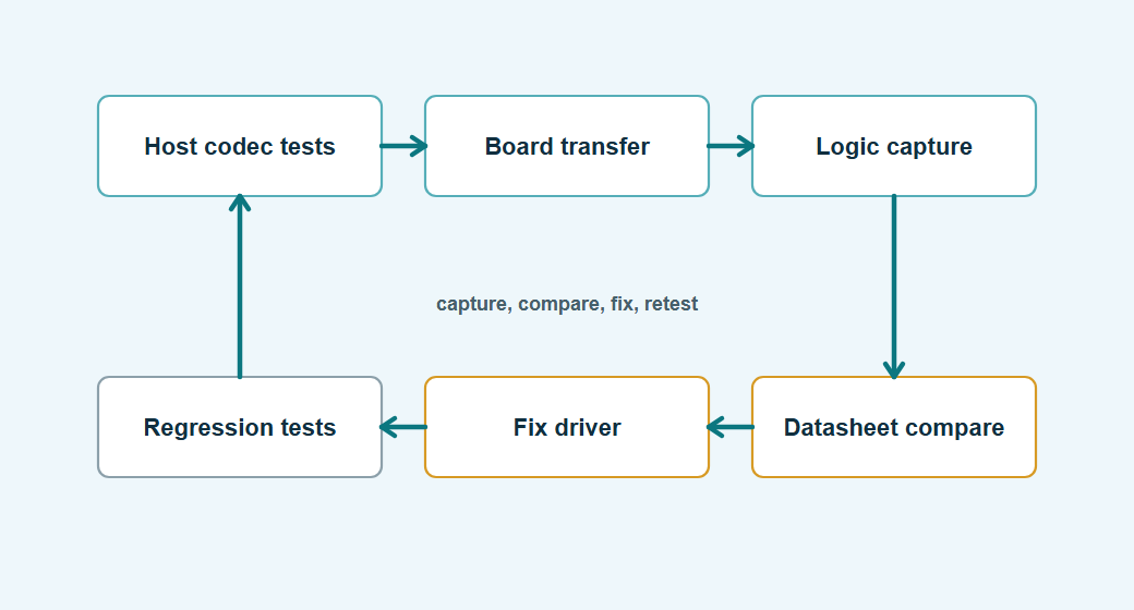
Lesson learned: The fastest bring-up sessions usually look boring. Read one known register, capture one transaction, compare it with the datasheet, then move to one measurement. Skipping straight to the acquisition task feels efficient until the first invalid sample has five possible causes.
Instead of starting with the complete acquisition task, start with the smallest observation that proves one layer at a time.
- Check power rails, reset pins, reference voltage, and chip-select idle level.
- Confirm the MCU SPI pins are mapped to the expected alternate functions.
- Read a device ID or reset-value register if the chip has one.
- Capture chip select, SCLK, MOSI, and MISO on a logic analyzer.
- Compare SPI mode, bit order, clock rate, and byte count against the datasheet.
- Read one fixed register repeatedly before enabling complex modes.
- Read one measurement in a slow blocking path before adding DMA or scheduler integration.
- Add burst reads, interrupts, and DMA only after the simple path is trustworthy.
This order may feel slow, but it is usually faster than debugging a full acquisition stack where the wrong SPI mode, wrong reference voltage, and wrong decoder all fail at once.
Make logic analyzer captures part of the review
A logic analyzer capture turns timing assumptions into something reviewable. Code can say the driver sends three bytes, but the capture shows whether chip select stayed low, whether the mode is right, and whether the response byte appears where the decoder expects it.
The value is highest when the capture is taken early and kept with the bring-up notes. Months later, when a board spin changes pullups or moves the device to another SPI instance, that old capture gives the team a concrete reference for what good looked like.
For a driver that talks to a new chip, the most useful review artifact is often a logic analyzer screenshot or decoded capture. It answers questions code alone cannot answer:
- Did chip select stay low for the whole transaction?
- Did the bus use the mode the datasheet requires?
- Was the first valid response byte ignored or used?
- Did the driver send the auto-increment bit for a burst read?
- Did another device on the bus drive MISO when it should not?
- Did the transaction length match the driver expectation?
The capture does not need to be beautiful. It needs to show the transaction that the driver claims to perform.
Keep calibration and compensation visible
Calibration code is part of the measurement path, not polish added after the driver is done. If gain, offset, trim, or compensation data is hidden in application code, the driver can no longer explain what its output means, especially when two products share the same chip but use different references, sensor placements, or calibration flows.
Keeping calibration data near the driver also helps debugging. You can log raw counts, corrected values, and calibration constants in one place, then decide whether the fault is electrical, protocol-level, or mathematical.
Many sensors and ADC front ends need calibration constants, trim values, gain correction, offset correction, or compensation formulas. Those rules should not be spread across application code. Read calibration data during initialization, store it in the device object, and apply it in the driver or a clearly named conversion layer.
Keep the raw format clear before calibration starts. Some ADCs return two's complement counts, some use offset binary, some left-align the useful bits, and some place status flags in the MSB. Decode that representation once, then make calibration operate on a named unit such as counts or microvolts. The snippet below shows the calibration state stored next to the SPI device and a conversion helper that applies gain and offset after the raw data has already been decoded.
|
1 2 3 4 5 6 7 8 9 10 11 12 13 14 15 16 17 18 19 20 21 22 23 24 25 26 27 |
/* AdcCalibration stores board or factory correction in named units. */ typedef struct { int32_t gain_ppm; int32_t offset_uv; } AdcCalibration; /* BoardAdc keeps the SPI device and its calibration data together. */ typedef struct { SpiChip spi; AdcCalibration cal; } BoardAdc; /* apply_adc_calibration works on decoded microvolts, not raw SPI bytes. */ static int32_t apply_adc_calibration(int32_t microvolts, const AdcCalibration *cal) { int64_t corrected = microvolts; corrected *= (1000000ll + cal->gain_ppm); corrected /= 1000000ll; corrected += cal->offset_uv; return (int32_t)corrected; } |
If the calibration formula comes from a datasheet, keep the variable names close enough that another engineer can compare code to the document without translating every symbol.
Avoid global scratch buffers
Global scratch buffers are easy to write during bring-up and hard to reason about once the driver is reused. They quietly assume one caller, one thread, no interrupt access, and no overlapping DMA. Those assumptions are often true on the bench and false in the product.
The debugging consequence can be ugly. A measurement task corrupts a configuration transfer, or an interrupt reads a sensor while a background task is using the same buffer. The bus capture looks fine, but the transmitted bytes are already wrong before they reach the SPI peripheral.
Global scratch buffers are convenient until two call sites use the driver at the same time, an interrupt reads data while a task writes configuration, or DMA completes after the caller has reused a buffer. Keep ownership clear. The code below passes scratch storage into the block-read helper, names every frame index, derives the transfer length once, and copies only payload bytes back to the caller.
|
1 2 3 4 5 6 7 8 9 10 11 12 13 14 15 16 17 18 19 20 21 22 23 24 25 26 27 28 29 30 31 32 33 34 35 36 37 38 39 40 41 42 43 44 45 46 47 |
/* Scratch constants define capacity, command position, payload start, and fill byte. */ enum { SPI_SCRATCH_CAPACITY = 16u, CHIP_BLOCK_COMMAND_INDEX = 0u, CHIP_BLOCK_FIRST_DATA_INDEX = 1u, CHIP_BLOCK_MAX_PAYLOAD = SPI_SCRATCH_CAPACITY - CHIP_BLOCK_FIRST_DATA_INDEX, CHIP_BLOCK_DUMMY_TX_BYTE = 0x00u }; /* SpiScratch gives the caller explicit ownership of temporary transfer buffers. */ typedef struct { uint8_t tx[SPI_SCRATCH_CAPACITY]; uint8_t rx[SPI_SCRATCH_CAPACITY]; } SpiScratch; /* chip_read_block performs command plus payload clocks without using global buffers. */ ChipStatus chip_read_block(SpiChip *chip, SpiScratch *scratch, uint8_t start_register, uint8_t *out, size_t length) { if ((chip == NULL) || (scratch == NULL) || (out == NULL) || (length > CHIP_BLOCK_MAX_PAYLOAD)) { return ChipStatus_BadParameter; } scratch->tx[CHIP_BLOCK_COMMAND_INDEX] = make_register_command(chip, start_register, true, true); size_t transfer_len = CHIP_BLOCK_FIRST_DATA_INDEX + length; for (size_t i = CHIP_BLOCK_FIRST_DATA_INDEX; i < transfer_len; ++i) { scratch->tx[i] = CHIP_BLOCK_DUMMY_TX_BYTE; } ChipStatus status = spi_chip_transfer(chip, scratch->tx, scratch->rx, transfer_len); if (status != ChipStatus_Ok) { return status; } for (size_t i = 0; i < length; ++i) { out[i] = scratch->rx[i + CHIP_BLOCK_FIRST_DATA_INDEX]; } return ChipStatus_Ok; } |
Passing scratch storage explicitly is not always necessary, but it makes ownership clear in drivers that may be called from more than one context.
Decide where the driver ends
This boundary keeps the driver reusable. If sampling policy, filtering, alarms, storage, or UI behavior leak into the chip driver, the next product has to drag along decisions that only belonged to one application.
A good driver should make correct hardware operation easy and wrong operation obvious, without deciding the whole system behavior. That split keeps the driver stable while the product around it changes.
A driver should know how to talk to the chip, configure it, read useful data, and report clear errors. It should not quietly own system policy unless that policy is truly part of the device.
Good boundaries:
- The ADC driver returns samples, overrange flags, and status.
- The sensor driver returns compensated measurements and data-ready state.
- The board layer owns GPIO pin mapping, SPI peripheral selection, and voltage-domain details.
- The application owns sampling rate policy, filtering policy, alarms, storage, and user-visible behavior.
This boundary matters when the product changes. If the application decides to sample at a different rate, you should not have to rewrite register encoding. If the board moves the chip to another SPI peripheral, you should not have to rewrite compensation math.
Common SPI driver mistakes
These mistakes share one theme: the code worked once with one setup, but the assumptions were never written down. The first board, first clock speed, first sample rate, and first caller then become invisible requirements.
The fix is not to make the driver complicated. The fix is to put each assumption in the right place: timing in the profile, byte layout in the codec, bus behavior in the transport, measurement meaning in the decoder, and system policy outside the driver.
These are the mistakes that show up repeatedly during bring-up:
- Using the wrong SPI mode because another chip on the bus configured the peripheral last.
- Forgetting that the first received byte was clocked during the command byte.
- Treating stale conversion data as a fresh sample.
- Missing the auto-increment bit for burst reads.
- Reading multi-byte values in the wrong byte order.
- Sign-extending after converting through the wrong type.
- Using fixed delays when a data-ready bit is available.
- Starting DMA from a stack buffer that goes out of scope.
- Sharing one global scratch buffer between task and interrupt contexts.
- Returning one generic error for every failure.
- Never checking device ID or reset-value registers during init.
Most of these are easy to avoid once the driver makes transactions, timing, decoding, and error categories explicit.
End-of-series driver checklist
Before considering a normal SPI chip driver ready, walk through the same categories you would use for an I2C driver: datasheet contract, public API, transport boundary, codec tests, and board bring-up. The details differ, but the review habit should be consistent across the driver series.
Datasheet and profile:
- The SPI mode, maximum clock, bit order, and chip-select timing are recorded in driver or board configuration.
- Chip-select setup, hold, inactive time, and reset delays use one named time representation after conversion from the datasheet.
- The profile names read masks, auto-increment masks, address width, dummy-byte count, status masks, conversion delays, and DMA limits where they apply.
- Register-map devices, command-style ADCs, and stream-like devices are not forced into one fake universal model.
API and transport:
- The public API talks in device concepts, not raw SPI buffers or command bytes.
- Register command construction is centralized.
- The driver knows which received bytes are dummy and which are valid.
- Multi-byte fields have one decoder with explicit byte order and sign handling.
- Conversion timing uses ready flags or named datasheet delays.
- Bus errors, timeouts, bad IDs, invalid samples, and overrange conditions are distinguishable.
- Shared SPI bus timing is applied per device.
- DMA use has a size threshold and clear buffer ownership.
- Calibration and compensation are kept close to the driver or clearly named conversion layer.
Host tests:
- Host tests cover command encoding, register helpers, burst helpers, response decoding, and bad parameter handling.
- Fake transports can inject bus errors, timeouts, not-ready responses, invalid IDs, and short or unexpected transfers.
- Tests cover receive-byte offsets, dummy clocks, stale data rules, byte order, sign extension, left alignment, and status-bit masking.
- Async state-machine tests cover start, wait, ready, timeout, read, decode, failure, and cancellation paths where the driver supports them.
- If a companion example project or shared driver repository exists, it builds the host tests and includes at least one register-map device profile and one command-style ADC example.
Board bring-up:
- Hardware bring-up includes logic analyzer confirmation of chip select, clock mode, MOSI command bytes, MISO response bytes, dummy clocks, and deselect timing.
- The first board test reads one known ID, reset-value register, or harmless status register before enabling the full acquisition path.
- Multi-device buses verify inactive-device MISO tri-state behavior, pull-ups or isolation resistors where needed, and per-device SPI peripheral reconfiguration.
- DMA testing includes buffer lifetime, alignment, cache maintenance, non-cacheable memory requirements, and transfer-complete execution context.
- Bring-up notes keep at least one known-good capture so later board revisions have a concrete reference.
Related vendor sources
These references are useful companion material when turning the patterns in this guide into a real driver. They show the controller side, the chip side, and the timing details that usually decide how clean the final driver becomes.
- STMicroelectronics STM32 HAL SPI APIs, useful for checking how blocking, interrupt, and DMA SPI transfers are exposed in the STM32 HAL.
- Infineon AURIX TC3xx QSPI training PDF, useful for AURIX projects where chip-select timing, frame format, queues, and DMA support belong in the QSPI configuration.
- Microchip MCP3204 and MCP3208 datasheet, useful for a small command-driven SPI ADC where command bits, dummy clocks, and sample timing are easy to inspect.
- Texas Instruments ADS1220 datasheet, useful for conversion commands, DRDY behavior, register access, calibration, and ADC data decoding.
- Analog Devices ADXL345 datasheet, useful for SPI register access, multi-byte reads, interrupt handling, and sensor data formatting.
Final takeaways
Writing an SPI driver is not only about making bytes move. The useful work is turning a chip datasheet into a small interface that the rest of the firmware can trust, review, test, and reuse.
The first successful SPI transaction is only the start. It proves that the pins, mode, and command shape are close enough to get a response. It does not prove that conversion timing is correct, that burst reads are coherent, that DMA buffer ownership is safe, or that the driver will survive the next board revision.
For simple chips, a good driver may only need a few helpers and a clean decoder. For ADCs, sensors, and front-end devices, it usually needs explicit conversion timing, status handling, scaling, calibration, and error categories. Those details are not ceremony; they are the difference between a driver you can debug in an afternoon and one that keeps producing unexplained field data.
Hardware abstraction matters because products change. The SPI peripheral may move, the board support package may change, the same chip may appear on another project, or a blocking transfer may need to become DMA later. If the driver already separates transport, command encoding, decoding, and application policy, those changes stay local. If it does not, every change becomes a search through unrelated application code.
The driver is done when the application can ask for the thing it actually needs, a voltage, a temperature, an acceleration vector, a register setting, or a data-ready state, and the SPI details stay where they belong. That is what makes the driver maintainable after bring-up excitement has faded.