
Part 3 of 3
Key patterns for Page 3
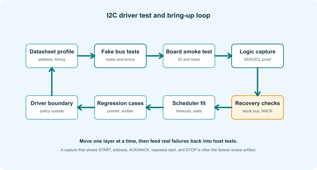
- Test transaction shape without hardware, then use hardware captures to prove the electrical bus did the same thing.
- Simulate NACKs, timeouts, stuck-bus recovery, endian mistakes, and invalid IDs before they happen on the bench.
- Keep chip revision, power state, and calibration data visible in the driver object.
- Let the board layer own pull-ups, level shifting, controller setup, and recovery sequences.
Test the codec without hardware
Host-side codec tests are valuable because they remove the board from the question. If the driver sends the wrong 7-bit address, builds the wrong register pointer, or accidentally uses separate write and read operations instead of a combined write-read, it will be wrong on the bench too. Catching that before probing a board saves time and keeps hardware debugging focused on hardware.
These tests also protect future edits. When someone adds a block read, changes a 16-bit register helper, ports the driver to a different controller API, or adds EEPROM page writes, the tests catch protocol drift before it becomes a measurement bug.
The following fake transport snippet shows what a useful host test can check. It verifies the address, pointer bytes, read length, and combined write-read behavior before returning fake data.
|
1 2 3 4 5 6 7 8 9 10 11 12 13 14 15 16 17 18 19 20 21 22 23 24 25 26 27 28 29 30 31 32 33 34 35 36 37 38 39 40 41 42 43 44 45 46 |
/* Note: The fake records the exact transaction shape the driver should emit. */ typedef struct { uint8_t expected_address_7bit; uint8_t expected_write[4]; size_t expected_write_len; uint8_t response_read[8]; size_t expected_read_len; bool saw_combined_write_read; } FakeI2c; /* Note: This fake validates address, write bytes, read length, and combined mode. */ static ChipStatus fake_write_read(void *user, uint8_t address_7bit, const uint8_t *write_data, size_t write_length, uint8_t *read_data, size_t read_length, uint32_t timeout_ms) { (void)timeout_ms; /* Note: user is the test fixture passed through I2cBusOps. */ FakeI2c *fake = (FakeI2c *)user; if ((address_7bit != fake->expected_address_7bit) || (write_length != fake->expected_write_len) || (read_length != fake->expected_read_len)) { return ChipStatus_BusError; } for (size_t i = 0; i < write_length; ++i) { if (write_data[i] != fake->expected_write[i]) { return ChipStatus_BusError; } } for (size_t i = 0; i < read_length; ++i) { read_data[i] = fake->response_read[i]; } /* Good: the test can assert that no separate STOP was inserted. */ fake->saw_combined_write_read = true; return ChipStatus_Ok; } |
These tests do not prove the electrical interface. They prove that the driver asks for the I2C transactions it claims to ask for. That is still a large part of the bug surface, especially for register-pointer, endian, repeated-start, and error-handling mistakes.
A useful host test set should include more than the happy path. At minimum, test the driver with:
- Every valid register pointer width and byte order used by the supported chips.
- Boundary register values such as 0x00, the last valid register, and one invalid register.
- Address NACK during probe, data NACK during a register write, timeout during readback, and a stuck-bus error.
- A fake device ID for the wrong chip and for a known alternate revision.
- Multi-byte payloads with swapped byte order, sign-extension edges, overrange flags, and stale-data flags.
- EEPROM page writes that end exactly at a page boundary and writes that would cross one.
For codec-style helpers, fuzzing small register values and payload lengths is cheap. It will not prove the hardware, but it often finds off-by-one indexes, missing bounds checks, and accidental page wrap before the board is available.
Bring up the hardware in layers
Layered bring-up keeps the number of unknowns small. If the first test is the full application, a missing pull-up, wrong address strap, unsupported clock stretching, bad level shifter, wrong register pointer, and decoder bug all collapse into the same symptom: bad data.
Start with the physical bus and one harmless transaction. I2C can fail quietly: SDA or SCL may be held low, pull-ups may be too weak for the chosen speed, a target may still be in reset, a level shifter may work at 100 kHz but fail at 400 kHz, or a connector may add enough capacitance that the waveform toggles while violating timing.
Lesson learned: The fastest I2C bring-up sessions usually look boring. Check that SDA and SCL idle high, read one known register, capture one combined transaction, compare it with the datasheet, then move to one measurement. Skipping straight to the acquisition task feels efficient until the first invalid sample has six possible causes.
Instead of starting with the complete application, start with the smallest observation that proves one layer at a time.
- Check power rails, reset pins, address pins, and I/O voltage domains.
- Confirm SDA and SCL idle high with the expected pull-ups installed.
- Verify the MCU pins are configured as open-drain or controller-managed I2C pins.
- Try one address probe or ID register read at a conservative bus speed.
- Capture SDA and SCL on a logic analyzer.
- Confirm START, address, ACK/NACK, repeated start, data bytes, final NACK, and STOP.
- Read one fixed register repeatedly before enabling complex modes.
- Read one measurement in a slow blocking path before adding interrupts, DMA, or scheduler integration.
This order may feel slow, but it is usually faster than debugging a full acquisition stack where the wrong address format, weak pull-ups, and wrong decoder all fail at once.
Make logic analyzer captures part of the review
A logic analyzer capture turns transaction assumptions into something reviewable. Code can say the driver uses a repeated start, but the capture shows whether the controller actually did it. Code can say the target NACKed the final byte, but the capture shows whether the controller acknowledged one byte too many before STOP.
The value is highest when the capture is taken early and kept with the bring-up notes. Months later, when a board spin changes pull-ups or moves the device behind a level shifter, that old capture gives the team a concrete reference for what good looked like.
For a driver that talks to a new I2C chip, the most useful review artifact is often a decoded capture. It answers questions code alone cannot answer:
- Did SDA and SCL idle high before the transaction?
- Did the controller send the expected 7-bit address?
- Did the target ACK the address and register pointer?
- Did the read use a repeated start instead of STOP followed by START?
- Did the controller NACK the final read byte before STOP?
- Did the target stretch SCL, and did the controller tolerate it?
- Did another device or a stuck target hold the bus low?
- Did the transaction length match the driver expectation?
The capture does not need to be pretty. It needs to show the transaction that the driver claims to perform.
Recover from a stuck bus deliberately
A stuck I2C bus is a board-level failure mode that software still has to handle. A target can hold SDA low after a reset during a transaction, the MCU I2C peripheral may time out and need reinitialization, or a sensor powered through leakage may keep one line clamped. If the driver only retries the same transfer, firmware can sit forever behind one blocked bus.
Bus recovery should live in the board transport or bus manager, not deep inside a sensor decoder. The recovery code may need to temporarily reconfigure SCL as GPIO, pulse SCL, generate a STOP condition, reset the controller peripheral, and then restore the I2C pins. That is hardware-specific behavior.
The bus-recovery snippet below shows why recovery belongs in the board layer. It temporarily owns the pins as GPIO, clocks SCL to release a stuck target, generates a STOP, and restores the controller.
|
1 2 3 4 5 6 7 8 9 10 11 12 13 14 15 16 17 18 19 20 21 22 23 24 25 26 27 28 29 30 31 |
/* Note: Recovery toggles board pins, so it belongs below the chip driver. */ ChipStatus board_i2c_recover_bus(BoardI2c *bus) { if (bus == NULL) { return ChipStatus_BadParameter; } board_i2c_disable_controller(bus); board_i2c_configure_lines_as_gpio(bus); /* Note: Up to nine clocks can release a target stuck mid-byte. */ for (unsigned i = 0u; i < 9u; ++i) { if (board_gpio_read_sda(bus)) { break; } board_gpio_drive_scl_low(bus); board_delay_us(5u); board_gpio_release_scl(bus); board_delay_us(5u); } /* Good: the board layer owns the electrical recovery sequence. */ board_i2c_generate_gpio_stop(bus); board_i2c_restore_controller_pins(bus); board_i2c_enable_controller(bus); return board_gpio_read_sda(bus) ? ChipStatus_Ok : ChipStatus_BusStuck; } |
The exact sequence depends on the controller, board, and targets. Recovery should also be serialized with the bus lock. In a multi-controller system, or on a bus that can be driven by another processor, recovery needs stronger coordination than a chip driver can provide.
Keep calibration and compensation visible
Calibration code is part of the measurement path, not polish added after the driver is done. If gain, offset, trim, or compensation data is hidden in application code, the driver can no longer explain what its output means, especially when two products share the same chip but use different references, sensor placements, or calibration flows.
Keeping calibration data near the driver also helps debugging. You can log raw counts, corrected values, and calibration constants in one place, then decide whether the fault is electrical, protocol-level, or mathematical.
Many I2C sensors and ADC front ends need calibration constants, trim values, gain correction, offset correction, or compensation formulas. Those rules should not be spread across application code. Read calibration data during initialization, store it in the device object, and apply it in the driver or a clearly named conversion layer.
The calibration snippet below shows how board trim can live next to the driver. It composes the reusable I2C chip object with ADC-specific calibration and uses wide math for ppm gain correction.
|
1 2 3 4 5 6 7 8 9 10 11 12 13 14 15 16 17 18 19 20 21 22 23 24 25 26 27 |
/* Note: Calibration stores board or production trim values beside the driver. */ typedef struct { int32_t gain_ppm; int32_t offset_uv; } AdcCalibration; /* Note: BoardAdc composes the generic I2C chip with ADC-specific calibration. */ typedef struct { I2cChip i2c; AdcCalibration cal; } BoardAdc; /* Note: Wide intermediate math avoids overflow during ppm gain correction. */ static int32_t apply_adc_calibration(int32_t microvolts, const AdcCalibration *cal) { int64_t corrected = microvolts; corrected *= (1000000ll + cal->gain_ppm); corrected /= 1000000ll; corrected += cal->offset_uv; return (int32_t)corrected; } |
If the calibration formula comes from a datasheet, keep the variable names close enough that another engineer can compare code to the document without translating every symbol.
Avoid global scratch buffers
Global scratch buffers are easy to write during bring-up and hard to reason about once the driver is reused. They quietly assume one caller, one thread, no interrupt access, and no overlapping asynchronous transfer. Those assumptions are often true on the bench and false in the product.
The debugging consequence can be ugly. A measurement task corrupts a configuration write, or a background EEPROM write reuses a buffer while an async transfer is still in progress. The logic analyzer capture shows wrong bytes on the bus, but the bug happened before the controller ever started the transaction.
Keep ownership explicit. Small blocking helpers can use stack buffers, while larger transfers may need caller-provided scratch storage, a driver-owned buffer protected by a lock, or a transport-managed DMA buffer. The right choice depends on concurrency and transfer size, but the choice should be visible.
The scratch-buffer snippet below shows explicit ownership for a block read. The caller provides storage that remains valid for the whole transaction, and the helper owns the 16-bit EEPROM pointer bytes.
|
1 2 3 4 5 6 7 8 9 10 11 12 13 14 15 16 17 18 19 20 21 22 23 24 25 26 27 28 29 30 31 32 33 34 35 36 37 38 39 40 41 42 43 44 45 46 47 48 |
/* Note: Scratch sizes define the largest safe blocking block transfer. */ enum { I2C_SCRATCH_CAPACITY = 18u, I2C_BLOCK_POINTER_INDEX = 0u, I2C_BLOCK_MAX_PAYLOAD = I2C_SCRATCH_CAPACITY - 2u }; /* Note: Caller-provided scratch keeps pointer and data buffers alive for the transfer. */ typedef struct { uint8_t pointer[2]; uint8_t data[I2C_BLOCK_MAX_PAYLOAD]; } I2cScratch; /* Note: The read helper owns the 16-bit memory pointer and output copy. */ ChipStatus eeprom_read_block(I2cChip *chip, I2cScratch *scratch, uint16_t offset, uint8_t *out, size_t length) { if ((chip == NULL) || (scratch == NULL) || (out == NULL) || (length > I2C_BLOCK_MAX_PAYLOAD)) { return ChipStatus_BadParameter; } scratch->pointer[0] = (uint8_t)(offset >> 8); scratch->pointer[1] = (uint8_t)offset; ChipStatus status = chip->bus.write_read(chip->bus.user, chip->profile.address_7bit, scratch->pointer, sizeof(scratch->pointer), scratch->data, length, chip->profile.timing.transaction_timeout_ms); if (status != ChipStatus_Ok) { return status; } for (size_t i = 0u; i < length; ++i) { out[i] = scratch->data[i]; } return ChipStatus_Ok; } |
Passing scratch storage explicitly is not always necessary, but it makes ownership clear in drivers that may be called from more than one context. If a driver uses internal scratch storage, document whether the driver is single-threaded, lock-protected, or async-safe.
Decide where the driver ends
A good driver should make correct hardware operation easy and wrong operation obvious, without becoming the whole application. It should know how to talk to the chip, configure it, read useful data, apply chip-specific compensation, and report clear errors. It should not quietly own system policy unless that policy is truly part of the device.
Good boundaries:
- The ADC driver returns samples, overrange flags, freshness, and status.
- The sensor driver returns compensated measurements and data-ready state.
- The EEPROM driver owns page boundaries and write-cycle polling.
- The GPIO expander driver owns register layout and interrupt flag handling.
- The board layer owns pins, pull-ups, voltage domains, controller setup, and bus recovery.
- The application owns sampling rate policy, filtering policy, alarms, storage, and user-visible behavior.
This boundary matters when the product changes. If the application decides to sample at a different rate, you should not have to rewrite register-pointer encoding. If the board moves the chip to another I2C controller, you should not have to rewrite compensation math. If a blocking transfer needs to become asynchronous, you should not have to change every caller that only wanted a temperature.
Account for variants, power, and host environment
Chip revisions are not rare. A newer revision may keep the same I2C address while changing reset values, adding status bits, altering conversion timing, or fixing a behavior that older firmware accidentally depended on. If the chip exposes an ID or revision register, read it once during initialization and select a profile or feature flags from that result. If it does not, keep the board-level part number and expected behavior in the profile.
Low-power firmware adds another boundary. If the MCU disables the I2C peripheral, changes pin states, or powers down a sensor rail, the driver should know whether cached configuration is still valid after wake. A practical pattern is to separate attach, init, suspend, and resume paths: attach binds the transport, init proves the device and writes configuration, suspend leaves the chip or bus safe, and resume restores only what may have been lost.
The same driver shape appears in larger environments, but the boundary moves. In Linux kernel drivers, the kernel I2C core owns adapters and clients. In Linux userspace, i2c-dev can be useful for tools and bring-up, but production device behavior often belongs in a kernel driver or a supervised service. In Zephyr, the i2c_dt_spec pattern moves address and bus selection into device tree. In Rust, embedded-hal encourages drivers that depend on traits instead of one MCU HAL. The design goal is the same: keep chip behavior separate from the transport that moves bytes.
One final edge case is trust. I2C is usually an internal board bus, not a secure communication channel. If a connector, replaceable module, or external cable exposes the bus, a device can spoof an address, hold lines low, or return plausible but false data. Most embedded products do not need cryptography on I2C, but safety or security-sensitive systems should not treat an ACK and a matching ID byte as proof of trust.
Common I2C driver mistakes
These mistakes share one theme: the code worked once with one setup, but the assumptions were never written down. The first board, first bus speed, first target address, and first caller then become invisible requirements.
The fix is not to make the driver complicated. The fix is to put each assumption in the right place: address representation in the profile, register-pointer layout in the codec, bus behavior in the transport, measurement meaning in the decoder, and system policy outside the driver.
These are the mistakes that show up repeatedly during bring-up:
- Passing an 8-bit address byte to a HAL that expects a 7-bit address.
- Splitting a required repeated-start register read into separate write and read transactions.
- Treating address NACK during EEPROM write cycle as a fatal device failure.
- Hiding clock-stretching timeouts behind a generic bus error.
- Assuming all multi-byte registers are big endian.
- Reading high and low measurement bytes in separate transactions when the datasheet requires a coherent block read.
- Forgetting that address pins change the low bits of the target address.
- Running the whole bus at 400 kHz when one target or board segment only works reliably at 100 kHz.
- Ignoring pull-up strength, bus capacitance, level shifters, or powered-off targets during software debugging.
- Retrying forever when SDA is physically stuck low.
- Using one global scratch buffer across task, interrupt, and async paths.
- Returning one generic error for address NACK, data NACK, timeout, bad ID, and invalid data.
Most of these are easy to avoid once the driver makes addressing, transaction shape, timing, decoding, and error categories explicit.
Practical reference checklist
Before considering a normal I2C chip driver ready, check the following:
- The 7-bit address and address-pin assumptions are recorded in driver or board configuration.
- The code does not confuse 7-bit target addresses with 8-bit address-plus-R/W bytes.
- The maximum bus speed, timeout, and clock-stretching expectations are recorded.
- The public API talks in device concepts, not raw I2C buffers.
- Register pointer construction is centralized.
- Required repeated-start transactions use one combined write-read transport call.
- Command-style devices are not forced into a fake register model.
- Multi-byte fields have one decoder with explicit byte order and sign handling.
- Conversion timing uses ready flags, ACK polling, or named datasheet delays.
- Address NACK, data NACK, timeout, bus stuck, bad ID, invalid sample, and not-ready status are distinguishable where recovery differs.
- Shared bus access is serialized across complete transactions.
- Board-level pull-ups, capacitance, level shifting, and voltage domains have been checked during bring-up.
- DMA or async use has clear buffer ownership and a size threshold or system reason.
- Host tests cover address use, register-pointer bytes, combined transactions, and response decoding.
- Hardware bring-up includes logic-analyzer confirmation of START, address, ACK/NACK, repeated start, data, final NACK, and STOP.
- Calibration and compensation are kept close to the driver or clearly named conversion layer.
- Unit tests cover NACKs, timeouts, stuck-bus recovery, invalid IDs, byte-order edges, and page-boundary limits.
- Power-management paths say whether configuration is retained, restored, or revalidated after wake.
- Chip variants and revisions are handled through IDs, profiles, or board-specific configuration instead of scattered conditionals.
Appendix: two compact mini-driver shapes
These are intentionally small examples, not complete production drivers. They show how the earlier patterns become ordinary code once the address, register pointer, timing, and data conversion rules have a home.
TMP117 temperature sensor mini example
This is a concrete TMP117 example, but still intentionally small. It assumes the board layer has already attached the I2C transport and timing to dev->chip, and it reuses the repeated-start register helper from Part 1. The TMP117-specific code owns the register names, ID check, configuration word, calibration offset, and temperature scaling.
The TMP117 mini-driver below ties the article patterns together for one concrete chip. It keeps TMP117 register names, ID masking, configuration generation, 16-bit helpers, and milli-Celsius scaling inside the driver.
|
1 2 3 4 5 6 7 8 9 10 11 12 13 14 15 16 17 18 19 20 21 22 23 24 25 26 27 28 29 30 31 32 33 34 35 36 37 38 39 40 41 42 43 44 45 46 47 48 49 50 51 52 53 54 55 56 57 58 59 60 61 62 63 64 65 66 67 68 69 70 71 72 73 74 75 76 77 78 79 80 81 82 83 84 85 86 87 88 89 90 91 92 93 94 95 96 97 98 99 100 101 102 103 104 105 106 107 108 109 110 111 112 113 114 115 116 117 118 119 120 121 122 123 124 125 126 127 128 129 130 131 132 133 134 135 136 137 138 139 140 141 142 143 144 145 146 147 148 149 150 151 152 153 154 155 156 157 158 |
/* Note: TMP117 register addresses, masks, and scaling live at the chip boundary. */ enum { TMP117_REG_TEMP = 0x00u, TMP117_REG_CONFIG = 0x01u, TMP117_REG_DEVICE_ID = 0x0Fu, TMP117_DEVICE_ID_MASK = 0x0FFFu, TMP117_DEVICE_ID_VALUE = 0x0117u, TMP117_CONFIG_CONT_4HZ_AVG_8 = 0x0220u, TMP117_CONFIG_AVG_MASK = (3u << 5), TMP117_CONFIG_AVG_32 = (2u << 5), TMP117_REGISTER_BYTES = 2u, TMP117_TEMP_LSB_MC_NUM = 78125, TMP117_TEMP_LSB_MC_DEN = 10000 }; /* Note: Board choices for address, offset, and averaging stay in the profile. */ typedef struct { uint8_t address_7bit; int32_t offset_mc; bool use_32_sample_average; } Tmp117Profile; /* Note: The concrete device combines the reusable I2C chip with TMP117 profile data. */ typedef struct { I2cChip chip; const Tmp117Profile *profile; } Tmp117; /* Note: TMP117 registers are read as big-endian 16-bit words. */ static uint16_t decode_be16(const uint8_t *raw) { return ((uint16_t)raw[0] << 8) | (uint16_t)raw[1]; } /* Note: Configuration generation is separate from bus transfer code. */ static uint16_t tmp117_config_word(const Tmp117Profile *profile) { uint16_t config = TMP117_CONFIG_CONT_4HZ_AVG_8; if (profile->use_32_sample_average) { config &= (uint16_t)~TMP117_CONFIG_AVG_MASK; config |= TMP117_CONFIG_AVG_32; } return config; } /* Note: All TMP117 16-bit register reads pass through one helper. */ static ChipStatus tmp117_read_u16(Tmp117 *dev, uint8_t reg, uint16_t *out) { uint8_t raw[TMP117_REGISTER_BYTES]; if ((dev == NULL) || (out == NULL) || (dev->chip.bus.write_read == NULL)) { return ChipStatus_BadParameter; } ChipStatus status = i2c_chip_read_registers(&dev->chip, reg, raw, sizeof(raw)); if (status != ChipStatus_Ok) { return status; } *out = decode_be16(raw); return ChipStatus_Ok; } /* Note: Writes send register pointer plus MSB and LSB in one frame. */ static ChipStatus tmp117_write_u16(Tmp117 *dev, uint8_t reg, uint16_t value) { uint8_t frame[3]; if ((dev == NULL) || (dev->chip.bus.write == NULL)) { return ChipStatus_BadParameter; } frame[0] = reg; frame[1] = (uint8_t)(value >> 8); frame[2] = (uint8_t)value; return dev->chip.bus.write(dev->chip.bus.user, dev->chip.profile.address_7bit, frame, sizeof(frame), dev->chip.profile.timing.transaction_timeout_ms); } /* Note: Init stores the profile, verifies identity, then writes configuration. */ ChipStatus tmp117_init(Tmp117 *dev, const Tmp117Profile *profile) { uint16_t device_id = 0u; if ((dev == NULL) || (profile == NULL)) { return ChipStatus_BadParameter; } dev->profile = profile; dev->chip.profile.address_7bit = profile->address_7bit; dev->chip.state.initialized = false; ChipStatus status = tmp117_read_u16(dev, TMP117_REG_DEVICE_ID, &device_id); if (status != ChipStatus_Ok) { return status; } /* Good: compare the device ID field without binding the driver to one revision nibble. */ if ((device_id & TMP117_DEVICE_ID_MASK) != TMP117_DEVICE_ID_VALUE) { return ChipStatus_BadId; } status = tmp117_write_u16(dev, TMP117_REG_CONFIG, tmp117_config_word(profile)); if (status != ChipStatus_Ok) { return status; } dev->chip.state.observed_device_id = device_id; dev->chip.state.initialized = true; return ChipStatus_Ok; } /* Note: The public read returns milli-Celsius with board offset applied. */ ChipStatus tmp117_read_milli_celsius(Tmp117 *dev, int32_t *out_mc) { uint16_t raw_word = 0u; if ((dev == NULL) || (dev->profile == NULL) || (out_mc == NULL)) { return ChipStatus_BadParameter; } if (!dev->chip.state.initialized) { return ChipStatus_NotReady; } ChipStatus status = tmp117_read_u16(dev, TMP117_REG_TEMP, &raw_word); if (status != ChipStatus_Ok) { return status; } int16_t counts = (int16_t)raw_word; /* Good: keep the exact scale in integer math, then round to milli-Celsius. */ int64_t scaled_mc = (int64_t)counts * TMP117_TEMP_LSB_MC_NUM; scaled_mc += (scaled_mc >= 0) ? (TMP117_TEMP_LSB_MC_DEN / 2) : -(TMP117_TEMP_LSB_MC_DEN / 2); *out_mc = (int32_t)(scaled_mc / TMP117_TEMP_LSB_MC_DEN) + dev->profile->offset_mc; return ChipStatus_Ok; } |
The profile keeps board-level choices out of application code: address straps, system calibration offset, and whether this board wants heavier averaging. For one-shot mode, add a separate start-and-poll path that sets MOD[1:0] to one-shot and watches the Data_Ready flag in bit 13 of the configuration register with a timeout. Do not hide that wait inside a function that looks like a simple cached temperature read.
24AA256-style EEPROM
This EEPROM-style example shows a different shape. The hard parts are not temperature scaling or data-ready flags. They are 16-bit memory offsets, page boundaries, bounded writes, and ACK polling after the internal write cycle starts.
The final snippet shows the EEPROM shape for comparison. It names the 24AA256 geometry, protects page boundaries, builds offset-plus-data frames, and uses ACK polling after a page write.
|
1 2 3 4 5 6 7 8 9 10 11 12 13 14 15 16 17 18 19 20 21 22 23 24 25 26 27 28 29 30 31 32 33 34 35 36 37 38 39 40 41 42 43 44 45 46 47 48 49 50 51 52 53 54 55 56 57 58 59 60 61 62 63 64 65 66 67 68 69 70 71 72 73 74 75 76 77 78 79 80 81 82 83 |
/* Note: EEPROM geometry and timing are named at the chip boundary. */ enum { EEPROM_24AA256_ADDRESS_7BIT = 0x50u, EEPROM_24AA256_PAGE_SIZE = 64u, EEPROM_24AA256_POINTER_BYTES = 2u, EEPROM_24AA256_MAX_WRITE_TIME_MS = 5u }; /* Note: The EEPROM wrapper reuses the generic I2C chip object. */ typedef struct { I2cChip chip; } Eeprom24aa256Lite; /* Note: Page-boundary checks prevent accidental wrap inside the EEPROM page buffer. */ static bool eeprom_write_crosses_page(uint16_t offset, size_t length) { size_t page_offset = (size_t)(offset % EEPROM_24AA256_PAGE_SIZE); return (page_offset + length) > EEPROM_24AA256_PAGE_SIZE; } /* Note: Reads send a 16-bit memory offset, then use a repeated-start read. */ ChipStatus eeprom24_read(Eeprom24aa256Lite *dev, uint16_t offset, uint8_t *out, size_t length) { uint8_t pointer[EEPROM_24AA256_POINTER_BYTES]; if ((dev == NULL) || (out == NULL) || (length == 0u)) { return ChipStatus_BadParameter; } pointer[0] = (uint8_t)(offset >> 8); pointer[1] = (uint8_t)offset; return i2c_chip_write_read(&dev->chip, pointer, sizeof(pointer), out, length); } /* Note: Page writes build one offset-plus-payload frame and then ACK-poll. */ ChipStatus eeprom24_write_page(Eeprom24aa256Lite *dev, uint16_t offset, const uint8_t *data, size_t length) { uint8_t frame[EEPROM_24AA256_POINTER_BYTES + EEPROM_24AA256_PAGE_SIZE]; if ((dev == NULL) || (data == NULL) || (length == 0u) || (length > EEPROM_24AA256_PAGE_SIZE)) { return ChipStatus_BadParameter; } /* Good: reject writes that would cross a physical EEPROM page. */ if (eeprom_write_crosses_page(offset, length)) { return ChipStatus_BadParameter; } frame[0] = (uint8_t)(offset >> 8); frame[1] = (uint8_t)offset; for (size_t i = 0u; i < length; ++i) { frame[EEPROM_24AA256_POINTER_BYTES + i] = data[i]; } ChipStatus status = dev->chip.bus.write(dev->chip.bus.user, dev->chip.profile.address_7bit, frame, EEPROM_24AA256_POINTER_BYTES + length, dev->chip.profile.timing.transaction_timeout_ms); if (status != ChipStatus_Ok) { return status; } // Good: wait for the internal write cycle with ACK polling. return i2c_wait_until_address_acks(&dev->chip, EEPROM_24AA256_MAX_WRITE_TIME_MS); } |
The public EEPROM API should usually split larger writes into page writes above this helper. Keeping the page rule here prevents a higher layer from accidentally creating a write that wraps inside one EEPROM page.
Useful primary references
These are good examples of the kinds of documents that force different I2C driver shapes:
- NXP UM10204 I2C-bus specification and user manual, useful for the base protocol, combined format, ACK/NACK behavior, clock stretching, addressing, and timing terms.
- Texas Instruments TMP117 datasheet, useful for a high-accuracy I2C temperature sensor with registers, conversion timing, configuration, and alert behavior.
- Microchip MCP23017 and MCP23S17 datasheet, useful for seeing how address pins, register maps, GPIO direction, pull-ups, interrupts, and sequential operation affect driver design.
- Bosch Sensortec BME280 datasheet, useful for register access, calibration data, compensation formulas, sensor modes, and both I2C and SPI interface behavior.
- Linux kernel Writing I2C Clients documentation, useful for seeing how Linux separates I2C adapters, clients, and kernel driver structure.
- Linux kernel i2c-dev userspace interface documentation, useful for bring-up tools and Linux userspace experiments.
- Zephyr I2C peripheral documentation, useful for RTOS driver boundaries, device-tree-backed bus selection, and controller APIs.
- Rust embedded-hal I2C traits, useful for portable driver design across MCU HAL implementations.
- Saleae I2C analyzer guide, useful for understanding what decoded captures can show during bring-up.
- Microchip 24AA256, 24LC256, and 24FC256 datasheet, useful for page writes, sequential reads, and ACK polling behavior.
- Texas Instruments ADS111x datasheet, useful for I2C ADC register pointers, configuration-driven conversions, and data-ready behavior.
Final takeaways
Writing an I2C driver is not only about making a target ACK. The useful work is turning a chip datasheet into a small interface that the rest of the firmware can trust, review, test, and reuse.
The first successful I2C transaction is only the start. It proves that the pins, address, and controller setup are close enough to get a response. It does not prove that repeated-start behavior is correct, that the register pointer is coherent, that conversion timing is fresh, that ACK polling is handled, or that the driver will survive the next board revision.
For simple chips, a good driver may only need a few helpers and a clean decoder. For ADCs, sensors, EEPROMs, and front-end devices, it usually needs explicit timing, status handling, scaling, calibration, error categories, and recovery behavior. Those details are not ceremony; they are the difference between a driver you can debug in an afternoon and one that keeps producing unexplained field data.
Hardware abstraction matters because products change. The I2C controller may move, the board support package may change, the same chip may appear with different address pins, or a blocking transfer may need to become asynchronous later. If the driver already separates transport, register or command encoding, decoding, and application policy, those changes stay local. If it does not, every change becomes a search through unrelated application code.
The driver is done when the application can ask for the thing it actually needs, a voltage, a temperature, an acceleration vector, EEPROM bytes, GPIO state, or a data-ready flag, and the I2C details stay where they belong. That is what makes the driver maintainable after the first ACK on the bench.